What you’ll take away
- A lever’s force advantage depends on force directions and perpendicular distances from its pivot.
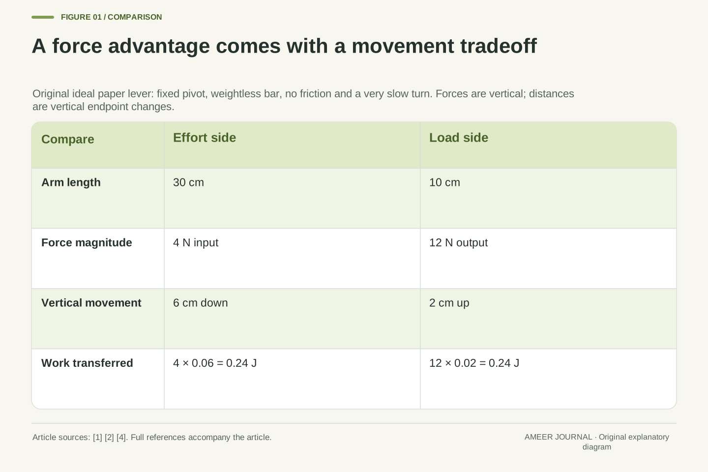
- The ideal 30 cm and 10 cm arms trade 4 N over 6 cm for 12 N over 2 cm.
- Force, turning effect and transferred work answer different questions.
- A fixed pivot can supply support without doing work through its stationary point.
- Real losses and stored-energy changes need their own energy account; a force advantage is not free energy.
A smaller push does not make the job disappear
Imagine a drawing of a straight bar resting on a pivot. One end is long and the other is short. A small downward force at the long end can balance a larger downward force at the short end. How can that happen without creating energy? The missing clue is movement. When the bar turns, the farther end moves more than the nearer end. A lever can exchange a smaller force for a greater distance of movement. It does not make the work of raising the same load through the same height vanish. This force–distance tradeoff is a central idea in simple-machine explanations. [1][2]
We will solve this puzzle entirely on paper with a grown-up. Drawings and number labels are enough; there is no need to build a lever, handle tools, balance your body, or lift anything. Our imaginary bar is rigid, its own weight is ignored, and its fixed pivot has no friction. We compare balanced positions and an ideal very slow movement, leaving starting and stopping effects out of the calculation. These rules make a small, clear model. They are not instructions for a real machine. The reward is an explanation of where the helpful force ratio comes from, what movement it requires, and which numbers a new drawing must provide.
The reader question is whether a force advantage implies a reduction in the mechanical work needed for a specified load displacement. For an ideal lever with no losses or net change in its own stored energy, input work equals useful output work. A larger output force is compensated by a smaller output displacement. OpenStax separates mechanical advantage, the ratio of output to input force magnitudes, from the conserved energy account. [1][2] Our original numerical model makes that distinction explicit rather than treating “easier” as a unit of work.
The activity is an adult-supported paper exercise with no physical construction or personal information. The model uses a massless rigid bar, a fixed frictionless pivot, vertical endpoint forces, and quasistatic motion: a sequence of almost-balanced states with negligible acceleration effects. Starting and stopping transients are outside this ideal account. The load rises while the effort point descends. We specify both force directions and endpoint displacement components, so a circular path is not mistakenly substituted for displacement along a vertical force. The example establishes force and energy relationships under declared assumptions, not the strength, stability or safe capacity of an actual lever.
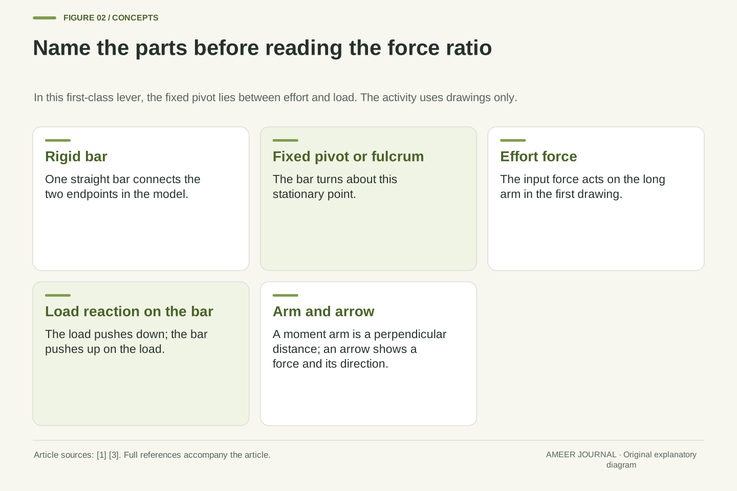
Label the pivot, the effort and the load
Draw a horizontal line for the bar and mark one point on it as the pivot, also called the fulcrum. The pivot is the fixed place about which the bar can turn. Put an effort arrow pointing down on the left and a load arrow pointing down on the right. The effort is the input force. The load arrow represents the downward force that the load exerts on the bar. With the pivot between them, this arrangement is called a first-class lever. University teaching material uses the relative positions of pivot, effort and load to distinguish lever arrangements. [1][3]
Now label the distance from the pivot to the effort point 30 centimetres, and the distance from the pivot to the load point 10 centimetres. These are the two arms of this drawing. The long arm is on the effort side. Be careful about one pair of arrows: the load pushes down on the bar, while the bar pushes up on the load. Those equal and opposite forces act on different objects. [1] Our drawing of forces on the bar must include the downward one. The pivot also supports the bar. A complete explanation will keep track of that support instead of pretending that only two forces exist.
Define the effort endpoint at x=−0.30 m and the load endpoint at x=+0.10 m relative to the pivot in the horizontal reference configuration. Both external endpoint forces on the bar point vertically downward. The pivot lies between the two force application points, giving a first-class arrangement. The bar's upward output force on the load is not an additional upward force acting on the bar. The corresponding load reaction on the bar is downward, as distinguished in the source's free-body treatment. [1][3]
Let Fe denote the input-force magnitude and Fo the upward output-force magnitude on the load; the downward reaction on the bar has magnitude Fo. Distances along the straight bar are re=0.30 m and ro=0.10 m. In the horizontal configuration, these also equal the perpendicular moment arms of the vertical forces. The pivot supplies an upward reaction but no moment about itself in this ideal model. The reference frame, direction convention and system boundary are now explicit. Using an upward output arrow in a diagram of forces on the bar would mix two different bodies and spoil the subsequent force balance.
Distance from the pivot changes the turning effect
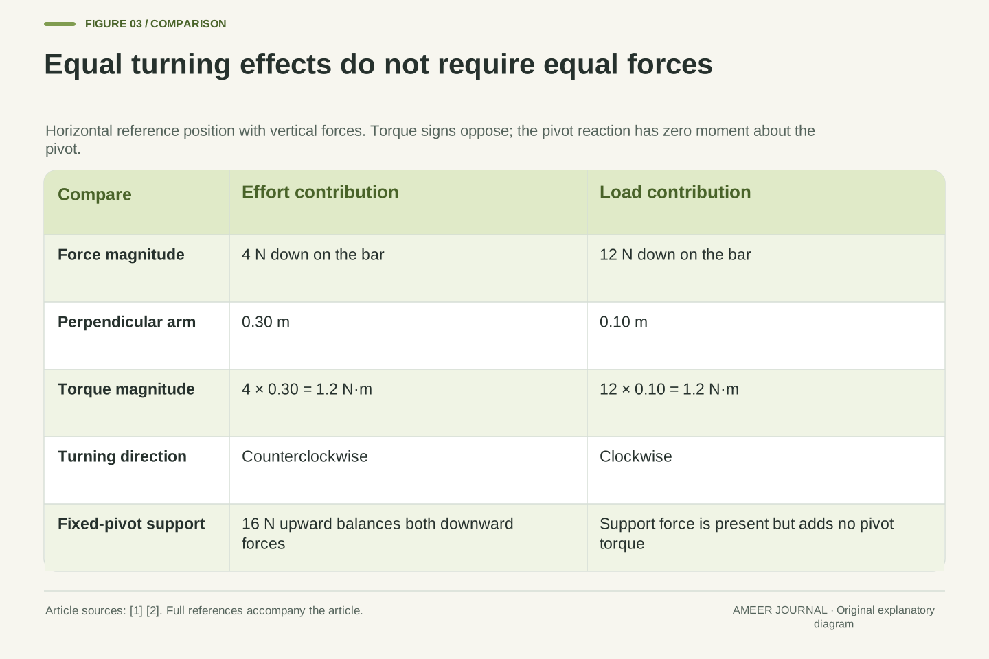
A force can have a turning effect about a pivot. That effect is called torque. The same downward force has a larger turning effect when applied farther from the pivot in our horizontal drawing. To compare the two sides, multiply each force by its arm length. A force of 4 newtons on the 30-centimetre arm gives the same turning-size calculation as 12 newtons on the 10-centimetre arm: 4×30 and 12×10 both equal 120. The two forces tend to turn the bar in opposite directions, so equal turning effects can balance. [1]
A newton is a unit of force, not a unit of mass. The letter N beside a number means newtons. Centimetres describe distance. Their product describes a turning effect in this particular comparison; it is not a new force of 120 N. We have also used a special geometry: the force arrows are perpendicular to the horizontal bar. More generally, the relevant distance is the shortest distance from the pivot to the line along which a force acts. [1] A long bar alone is not enough information. We will return to direction later, after following the clearly labelled vertical arrows in this first drawing.
For a force acting in a plane, the torque magnitude about the pivot is force magnitude multiplied by the perpendicular distance from the pivot to its line of action. In the stated horizontal-bar geometry, the vertical endpoint forces have moment-arm magnitudes re and ro. Taking counterclockwise as positive gives τe=Fe re and τload=−Fo ro. Static rotational balance therefore requires Fe re=Fo ro. The pivot reaction contributes zero torque about the pivot. [1]
This is a moment equation, not a sum of force magnitudes. It permits a small force with a large moment arm to balance a large force with a small moment arm. The centimetre calculation 4×30=12×10 produces equal magnitudes of 120 N·cm, or 1.2 N·m. The opposite signs cancel in the net torque. The horizontal assumption matters because a distance measured along an angled bar need not itself be the perpendicular moment arm. For vertical forces on the same straight bar at angle θ to horizontal, the two moment arms become re cos θ and ro cos θ in magnitude within the chosen near-horizontal range. Their common factor cancels away from a vertical singular orientation.
Follow the 12-newton load through the balance
Give the load arrow the label 12 N. The load arm is 10 cm and the effort arm is 30 cm, three times as long. Our balance rule asks for an effort force three times smaller: 4 N. The mechanical advantage is the output force divided by the input force, so this ideal arrangement has an advantage of 12÷4=3. [1][2] It does not mean that the bar has made three times as much energy. We have compared forces only. We still need to find how far the two ends move.
The 4 N value balances the load in the model. A perfectly balanced bar at rest does not suddenly begin turning by itself. To describe gentle movement, we use the ideal limit of a very slow turn and leave its small starting and stopping effects aside. The pivot also matters: the downward forces on our weightless bar total 4+12=16 N, so the pivot's support is 16 N upward in a balanced position. That support has no turning effect about the pivot itself. The numbers make sense together once we ask two separate questions: do the forces balance, and do their turning effects balance?
Substitution into Fe re=Fo ro gives Fe=12×0.10/0.30=4 N. The ideal mechanical advantage is Fo/Fe=re/ro=3. The torque magnitudes are each 1.2 N·m. Vertical force balance on the massless bar requires R−Fe−Fo=0, so the upward pivot reaction is R=16 N. This reaction is necessary for translational equilibrium even though its moment about the chosen pivot vanishes. Output force on the load remains upward; the equal-magnitude reaction on the bar remains downward. [1]
Exactly balanced torque with an initially stationary real system does not establish motion. The force ratio used for the work calculation is the quasistatic limiting ratio, with negligible acceleration and no losses. Under constant vertical endpoint forces, both torque magnitudes acquire the same cosine factor as the rigid bar rotates through the specified near-horizontal movement, so the ratio remains three. The model does not assert that an arbitrary finite acceleration follows from zero net torque. Separating equilibrium, slow-motion idealization and acceleration avoids interpreting a balancing-force calculation as a complete time-dependent simulation. No speed, starting impulse or lifting time has been predicted.
The longer end has farther to go
Imagine two positions of the same drawn bar, one horizontal and one slightly turned. The load point on the short arm rises while the effort point on the long arm falls. Both ends belong to the same rigid bar and turn through the same angle about the pivot. Because one arm is three times the length of the other, its vertical movement is three times as large for this turn. The force advantage therefore comes with a movement tradeoff. This link between effort travel and load travel is part of the ideal-machine relationship. [2]
Choose a turn in which the load point rises 2 cm. The effort point must fall 6 cm, not 2 cm. We are comparing vertical changes in position because our forces point vertically. The curved path of an endpoint is a different distance. The pivot itself stays in the same place. If a drawing claimed both a three-times larger output force and exactly the same input and output travel in this loss-free arrangement, something would be wrong with its labels. Following the two positions together helps reveal the missing tradeoff. A smaller push can help with a task precisely because it is allowed to act through more movement.
For a straight rigid bar rotating from horizontal through an angle θ, the load endpoint's upward displacement is ho=ro sin θ and the effort endpoint's downward displacement magnitude is he=re sin θ. Their ratio is therefore he/ho=re/ro=3 for a nonzero turn in the stated range. Choose ho=0.02 m with ro=0.10 m, so sin θ=0.2. The corresponding effort displacement is he=0.30×0.2=0.06 m. This is an exact geometric relation for the declared positions, not a small-angle replacement of sin θ by θ.
The endpoints also change horizontal position, but those components contribute no work from the stipulated constant vertical forces. Circular arc lengths reθ and roθ are not the distances to multiply by these vertical force magnitudes. Work requires the component of displacement along the force, or an equivalent dot-product calculation. [4] The familiar ideal-machine travel ratio remains useful here because the same geometry fixes both vertical components. [2] The fixed pivot has zero displacement, so its reaction transfers no work at the pivot despite being a nonzero supporting force. Force support and energy transfer are consequently separate parts of the model.
Calculate work with force and movement together
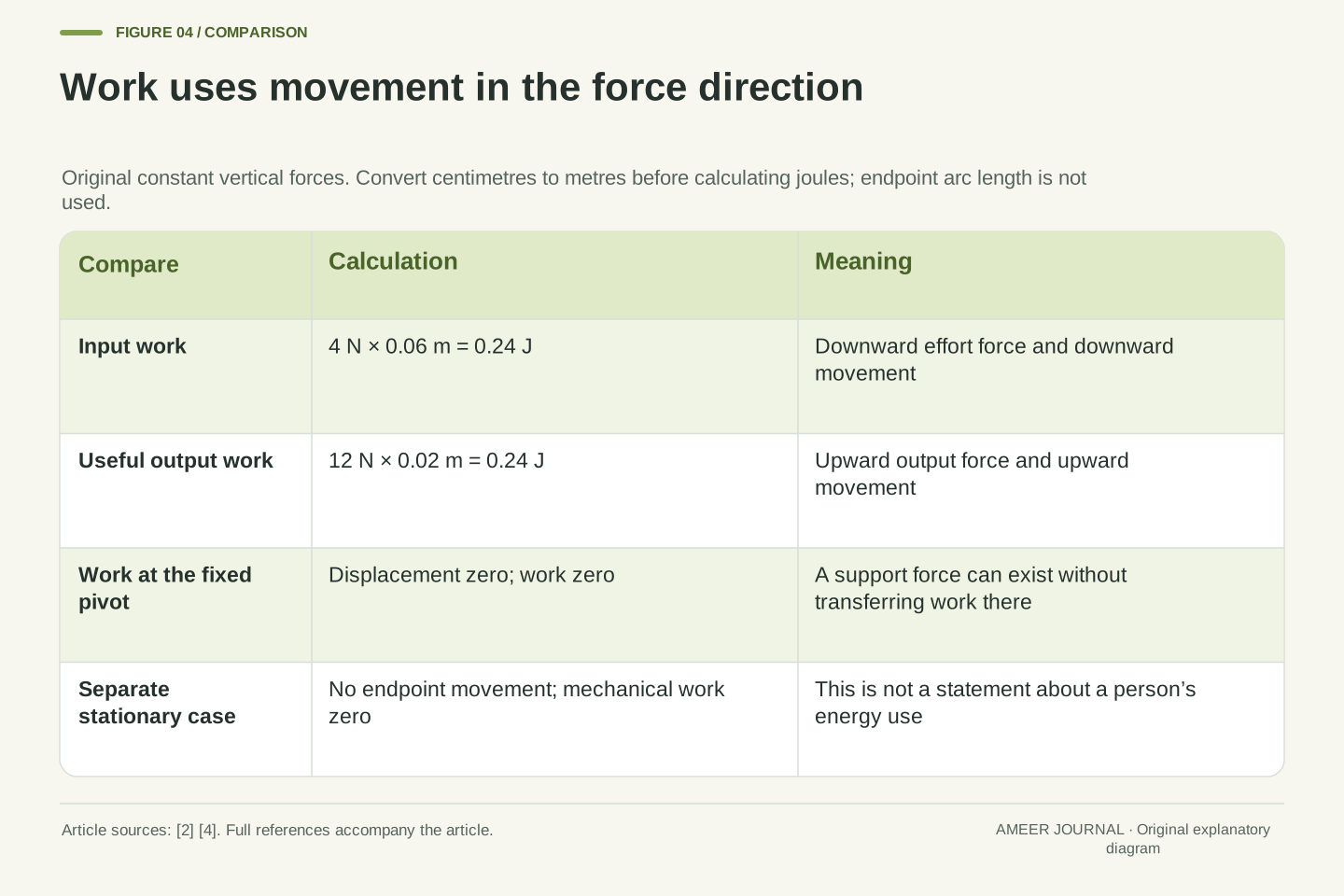
In science, work describes energy transferred by a force acting through displacement. For our constant vertical forces, multiply force by vertical movement. [4] On the effort side, 4 N acts through 6 cm. On the load side, 12 N acts through 2 cm. Both products are 24 newton-centimetres. To express the result in joules, the usual unit of energy, change centimetres to metres first: 6 cm is 0.06 m and 2 cm is 0.02 m. The input is 4×0.06=0.24 joule. The useful output is 12×0.02=0.24 joule too.
The force became three times larger while its distance became three times smaller. Their product stayed the same. Nothing in that calculation supplies extra energy. Now imagine a separate drawing in which the endpoints do not move at all. The forces can still be present and balanced, but they do no mechanical work through those stationary points during that interval. [4] That statement is about the particular object and force being described. It is not a claim that a person feels no effort or uses no energy while holding something still. A grown-up can help keep the everyday meaning of “work” separate from this more specific scientific calculation.
The constant vertical input force does positive work Win=Fe he=4×0.06=0.24 J because its application point moves downward with the force. The lever does positive useful work on the rising load, Wout=Fo ho=12×0.02=0.24 J. The load's downward reaction does −0.24 J on the bar. Thus the net work on the ideal bar is zero; the pivot reaction contributes zero because its application point is fixed. One joule is one newton-metre for work. [4]
Torque and work share force-times-length dimensions but use different relationships. Torque uses perpendicular separation from a pivot and characterizes a turning tendency. Work uses displacement along a force and characterizes energy transfer. Our 1.2 N·m torque magnitude is therefore not a claim that 1.2 J has been transferred. The chosen motion transfers 0.24 J on each useful side. In the separate stationary case, displacement is zero and the mechanical work by each force through its fixed application point is zero. That system-level statement does not describe a person's metabolic expenditure. Keeping the system and displacement explicit prevents a correct mechanics equation from becoming an unsupported physiological claim.
Moving the drawn pivot changes both sides of the trade
Keep the same 12 N load, but compare three drawings of a 40 cm bar. In the first, the pivot divides it into two 20 cm arms. The two turning distances are equal, so the balancing effort is 12 N. In the second, the effort arm is 30 cm and the load arm 10 cm, giving our earlier effort of 4 N. In the third, reverse those lengths: effort arm 10 cm, load arm 30 cm. Now the balancing effort must be 36 N. A lever does not always make the input force smaller. Its arrangement matters. [1][3]
Ask every drawing to raise its load point by the same 2 cm. The equal-arm drawing needs 2 cm of effort movement. The long-effort-arm drawing needs 6 cm. The short-effort-arm drawing needs only two-thirds of a centimetre, but requires the larger 36 N force. In each ideal case, the force–distance product gives the same 0.24 joule of useful output. These are three different labelled geometries, not three measurements. One can favour a smaller input force; another can favour a greater output movement for a given input movement. Calling one drawing “best” needs a stated aim. The word lever by itself cannot choose the useful arrangement.
Let the total straight bar length remain 40 cm and compare effort/load arm pairs of 20/20, 30/10 and 10/30 cm. For the fixed Fo=12 N, Fe=Fo ro/re gives 12, 4 and 36 N respectively. The corresponding ideal mechanical advantages are 1, 3 and 1/3. A first-class arrangement can therefore provide a force advantage, equality or a force disadvantage, consistent with the source treatment of relative fulcrum position. [1][3]
For a specified output rise ho=2 cm in each geometry, he=(re/ro)ho gives 2, 6 and 2/3 cm. Multiplying each input force by its corresponding displacement in metres yields 0.24 J in all three cases. The output-force magnitude and rise are unchanged; the input combination changes. The three turns need not have the same angle because the output arm lengths differ, but each individual bar's two endpoints share its own turn. The ratio concerns paired displacements within one geometry, not a comparison that assumes all three bars rotate identically. These ideal ratios also do not determine task completion time without a specified input motion or power. A distance advantage is not, by itself, a measured speed improvement.
A long arm is useful only with the right force direction
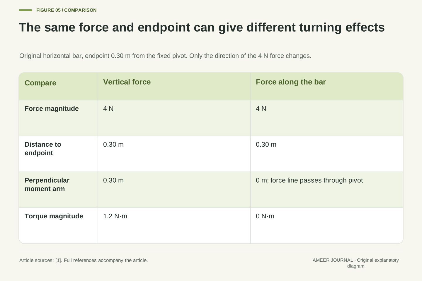
Return to the horizontal bar with its 30 cm effort arm. Draw a 4 N arrow straight down at that endpoint. Its turning-effect magnitude is 4×30=120 newton-centimetres. Now make a second drawing with a 4 N arrow pointing along the bar toward the pivot instead. That line of force passes directly through the pivot, so this force has no turning effect about the pivot in our ideal picture. The distance to the endpoint is still 30 cm, but the perpendicular distance to the force's line is now zero. [1]
This comparison explains why “push farther away” is an incomplete rule unless the direction is understood. A drawing needs arrows, positions and a fixed pivot, not just a bar length and a number. It also needs to show which object receives each force. A long arrow is sometimes used to represent a large force, but it is not the lever arm. The arm is a distance measured from the pivot to the force's line in the relevant way. You can point to those separate features on the page. When a clue is missing, identifying that missing clue is more useful than inventing a force advantage from the bar's appearance.
Compare two input forces of magnitude 4 N at the endpoint 0.30 m from the fixed pivot. In the horizontal reference configuration, a vertical downward force has perpendicular moment arm 0.30 m and torque magnitude 1.2 N·m. A force directed along the bar has a line of action through the pivot, giving perpendicular moment arm zero and torque zero about that pivot. This is an original application of the source's perpendicular-arm definition. [1]
The contrast does not require a change in force magnitude or application-point distance. It changes the angle between position and force. Equivalently, the torque magnitude is rF|sin φ|, where φ is the angle between the pivot-to-point vector and the force vector. The vertical-force case has |sin φ|=1; the along-bar case has |sin φ|=0. This formula concerns torque, whereas the cosine factor in the work definition concerns the angle between force and displacement. Confusing those two angles would reverse the reasoning. A complete paper record should identify pivot, application point, force direction and movement separately. The arrows describe an analytical comparison, not directions for applying force to a real object.
Real losses change the energy account
Our first drawing deliberately left out friction and other losses. Real moving parts can transfer some input energy into heating and other effects instead of the useful lifting task. [2] Consider a separate imaginary energy card: 0.30 joule goes in, and 0.24 joule reaches the useful output. Suppose the machine finishes with the same stored energy it started with. The remaining 0.06 joule must then leave through other paths, such as heating the surroundings. Energy has been accounted for; it has not disappeared.
The useful-output share is 0.24÷0.30=0.8, or 80%. This share is called efficiency. It is different from the force ratio called mechanical advantage. [2] The 80% belongs only to this invented energy card. It is not a fact about every lever, or a result from a test we performed. Even a useful force advantage does not prove that all the input energy reaches the desired job. If the machine were storing or releasing energy during the interval, we would need that extra clue before calculating the other transfers. Keeping the ideal drawing and this separate loss example labelled helps us use a simple model without pretending that its omitted effects never occur.
For a stated interval, use Win=Wout+Eother+ΔEmachine, where Wout is useful output work and Eother represents other outward energy transfers. In a separate hypothetical case, let Win=0.30 J, Wout=0.24 J and ΔEmachine=0. Then Eother=0.06 J and useful efficiency η=Wout/Win=0.8=80%. The source defines efficiency as output work divided by input work and discusses frictional conversion of useful mechanical energy. [2]
These values are a declared energy account, not an observed friction coefficient or an inferred device specification. The original ideal force calculation has not secretly acquired an extra loss term. Mechanical advantage Fo/Fe and efficiency Wout/Win are different dimensionless ratios; a force gain is not an energy gain. If the mechanism changes its kinetic, elastic, thermal or other stored energy between the chosen endpoints, ΔEmachine must remain in the balance. Our zero-storage-change assumption closes this particular account. Similarly, an actual input force cannot be recovered from an energy total without the relevant motion and force history. The example supplies enough information to calculate an efficiency, while leaving unsupported details of a real mechanism undecided.
Read a new lever drawing before choosing an answer
Try a final paper card with a grown-up. It gives an effort arm of 20 cm, a load arm of 10 cm and a 12 N load, with the same ideal horizontal-bar and vertical-force rules. The effort arm is twice as long, so a balancing effort of 6 N follows. If the load point rises 2 cm, the effort point moves down 4 cm. The work calculation is 6×0.04=0.24 joule in and 12×0.02=0.24 joule out. Check the force clue and the movement clue together instead of stopping after the smaller force.
Now imagine that the arrow directions are erased, leaving only lengths and force sizes. You need the directions to know the turning effects. If the movement labels are erased instead, you can discuss balance under the stated force directions but cannot calculate a particular amount of transferred work. Those are useful answers because they identify what is missing. No score, name, photograph or uploaded drawing is needed. The central lesson is a connected explanation: the pivot and force directions define the turning distances; their ratio defines the ideal force tradeoff; the shared turn defines the travel ratio; and force together with movement gives work. A smaller input force can be helpful while the energy required for the stated useful task remains accounted for.
The final original card has re=0.20 m, ro=0.10 m and Fo=12 N, giving Fe=6 N and ideal mechanical advantage two. With ho=0.02 m, the paired input displacement is he=0.04 m. Both useful work calculations give 0.24 J. These deductions reuse the declared geometry and ideal conditions, not a memorized claim that every lever multiplies force. If force directions are unspecified, endpoint lengths alone do not determine moment arms; if displacement is unspecified, equilibrium alone does not determine transferred work. [1][4]
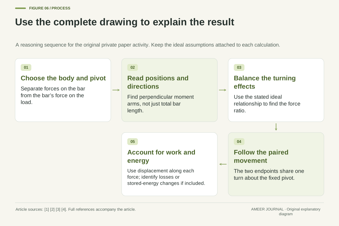
A complete explanation therefore preserves four distinct relationships: force balance on the selected body, torque balance about the fixed pivot, geometric compatibility of endpoint motion, and the energy account. The pivot reaction is relevant to the first and contributes no moment or work about its own fixed location. The arm ratio controls the second and third under the stated force directions. The work equation connects force with displacement and distinguishes ideal transfer from losses or storage changes. [1][2][4] Adult discussion can follow those relationships through the private drawing at the child's pace. The paper exercise offers an inspectable chain of reasoning without claiming experimental validation, real-machine safety or a universal preference for one lever arrangement.
Sources & further reading
Explore the references behind this guide. External pages may change after our review.
- 9.5 Simple Machines - College Physics | OpenStaxOpenStax / Rice University · Accessed 6 Nov 2026
- 9.3 Simple Machines - Physics | OpenStaxOpenStax / Rice University · Accessed 6 Nov 2026
- Levers That Lift - Lesson - Teach EngineeringTeachEngineering / Integrated Teaching and Learning Program, University of Colorado Boulder · Accessed 6 Nov 2026
- 7.1 Work: The Scientific Definition - College Physics | OpenStaxOpenStax / Rice University · Accessed 6 Nov 2026
Article updated 6 Nov 2026.