What you’ll take away
- A shadow forms where an obstacle reduces the light reaching a region; it is not a reflection or a dark substance.
- The same upright post can cast different shadow lengths when the incoming light direction changes.
- Height ratios match shadow-length ratios only under the stated shared projection conditions.
- A nearby point source can give equal-height posts different shadow lengths at different positions.
- Identifying a missing light or surface clue is a useful answer when the shadow alone cannot determine height.
Does the longest shadow belong to the tallest object?
Two drawings show an upright post and its shadow. One shadow is twice as long as the other. Can you immediately say which post is taller? Only if the drawings give you enough information about the light and the surface. A shadow's length depends on more than the height of the object blocking the light. The position and direction of the light matter too. Science Learning Hub explains that changing the light source's position can change a shadow's size and shape. [1][3] We will turn that idea into a puzzle with answers that can be checked.
Explore the puzzle on paper with a grown-up. You only need to read the drawings and number labels or sketch simple lines. There is no need to use a lamp, torch, laser, flame, tool or camera, go outside, or look toward the Sun. No name, photograph, location or uploaded work is needed. Our numbers belong to invented side-view models, not measured shadows. Each drawing uses the same unit for vertical and horizontal distances, such as equal squares on a drawn grid. We will first keep the rules simple, then change one important rule to see when a comparison stops working.
The question is whether shadow length alone determines object height. In geometric optics, projected shadow size depends on source geometry, object geometry and the receiving surface. University teaching resources explicitly connect size and shape with source and object positions. [1][3] The article uses original side-view constructions to separate a valid proportional comparison from an underdetermined one. The purpose is to identify the conditions needed for an inference, not to make every shadow into a convenient height measurement.
This is an adult-supported private paper activity. No physical light source, solar viewing, tools, outdoor measuring or personal information is involved. The first model uses a thin upright opaque post, a horizontal receiving surface, uniform straight rays with one common direction, and no other illumination. The post's width is ignored in this side view; shadow length runs horizontally from its base to the far tip. Heights and distances share one model unit. We later replace the parallel rays with a nearby point source to show that the original proportional rule depends on its illumination assumption.
A shadow is a place receiving less light
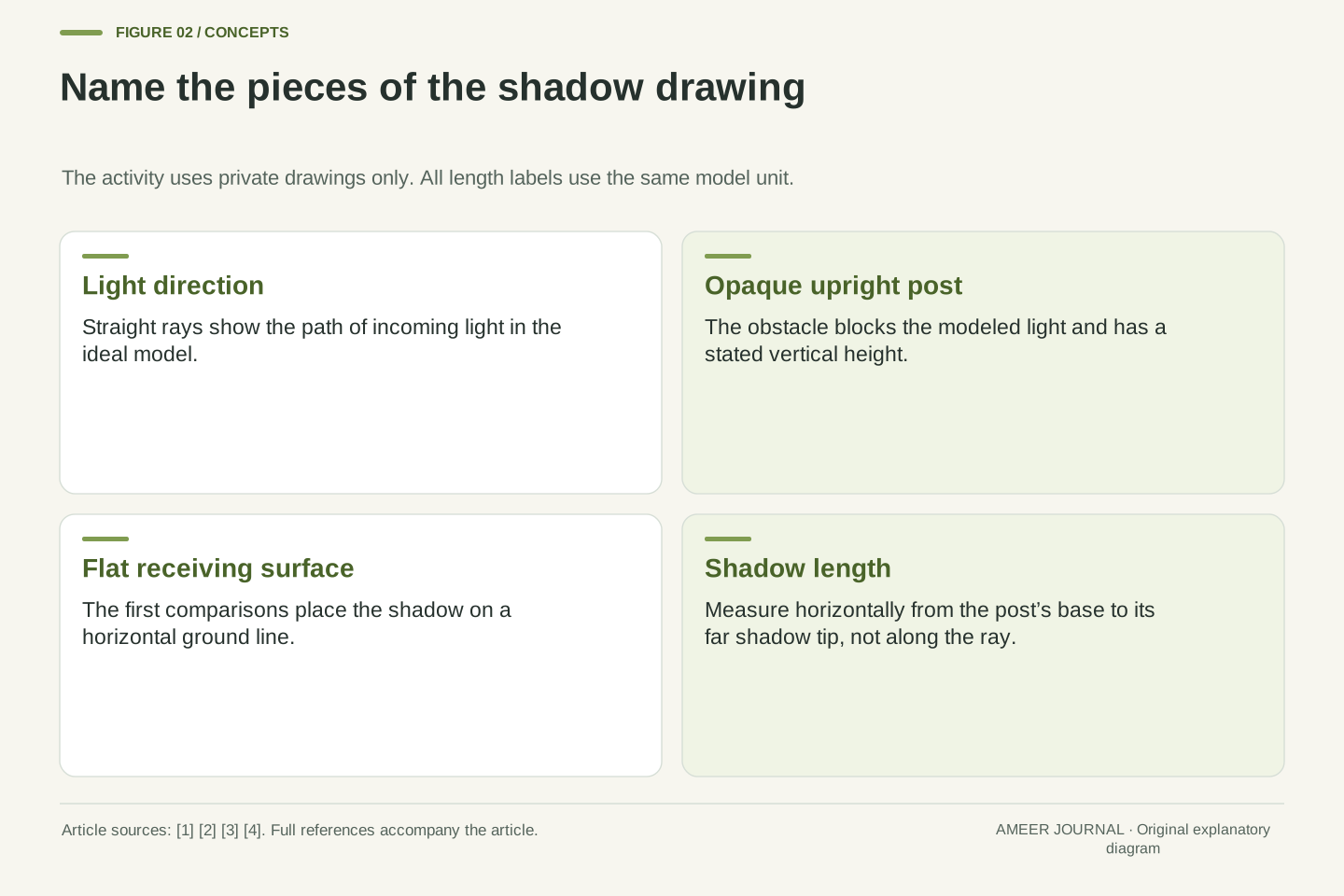
A shadow is not a dark material that comes out of an object. It is a region that receives less light from a source because something blocks the light's path. In our drawing, the post is opaque: the light in the model does not pass through it. The post stands between the source and the part of the surface that it shades. A shadow is also different from a reflection, which involves light bouncing from a surface. These distinctions help explain why changing the light can change a shadow without changing the object. [1][3]
Real shadows do not always look completely black. Light can reach a shaded area by other routes, including reflection from nearby surfaces. Science Learning Hub discusses this extra illumination when explaining why shadows can remain partly lit. [4] Our first drawings leave it out so that one blocked direction and one shadow edge are easy to follow. That is a model choice, not a claim that every real room has only one path for light. The model will answer a particular geometry question: where does the boundary ray passing the top of the post meet the flat surface?
For the chosen source, an opaque obstacle removes direct paths that would otherwise reach part of the receiving surface. The resulting reduction in illumination is a shadow. It is not a separate emitted substance or a reflected image of the object. The source–object–receiver relationship is central in the educational material. [1][3] Specifying the source matters because a region shadowed from one source may still receive light from another source or from reflected paths.
The initial model deliberately has a single directional illumination field and a sharp geometric boundary. It suppresses indirect light, transmission, finite source extent and diffraction so that the intersection of one limiting ray with the ground defines the far tip. Source material notes reflected light in shadows and the effects of source extent on edge definition. [3][4] Those mechanisms will return when interpreting the model's limits. Treating a drawn dark region as an ideal blocked-light set is useful here, provided its edge and length are not mistaken for a complete description of real surface brightness.
Give the drawing a rule for the light direction
Draw a flat ground line and an upright post above it. Imagine straight light paths slanting downward from left to right. A line representing a light path is called a ray. The ray model describes light using straight paths when the conditions make that a useful approximation. [2] For our first set of cards, all incoming rays have the same slant. They are parallel, meaning that they stay the same distance apart instead of spreading from a nearby dot.
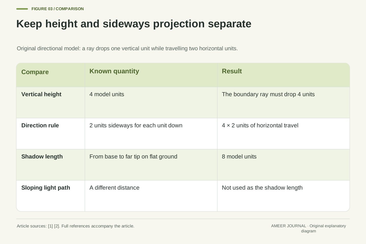
Give the slant an easy counting rule: while a ray drops one vertical unit, it travels two horizontal units. A ray passing the top of a four-unit post must drop four units to reach the ground. It therefore travels eight units sideways, placing the shadow tip eight units from the post's base. This horizontal distance is the shadow length. It is not the length of the sloping ray. Keeping the upright height, sideways shadow and sloping light path separate prevents three different distances from being confused. You can follow the count with a grown-up without measuring a real shadow.
Set the post base at (0,0) and its top at (0,h), with h>0. Let the relevant rays travel downward to the right at an elevation angle α above the horizontal when traced back toward their source, where 0<α<90°. A boundary ray passing the top has equation z=h−x tan α. Its ground intersection z=0 occurs at x=L=h/tan α. This is an original geometric deduction using the straight-ray model described by OpenStax. [2]
Define k=cot α as horizontal travel per unit vertical drop. Then L=kh. The ratio k is dimensionless, while h and L use the same length unit. It is a direction parameter, not brightness, elapsed time or the sloping distance from source to post. For k=2 and h=4, L=8. Because every incoming ray in this model shares k, different posts on the same horizontal plane can be compared by proportionality. That shared direction is a stated geometric condition, not something established merely by drawing a light symbol somewhere on the page.
A second construction reaches the same endpoint without an angle calculation. Write a ray direction as (k,−1) and start at the post top (0,h). After a vertical drop u, its coordinates are (ku,h−u). Ground contact requires u=h, which gives the endpoint (kh,0). This parameterization makes the horizontal projection visible and shows why the two components must use compatible length scales.
The same post can have three different shadow lengths
Keep the post four units tall and change only the ray rule. In the first drawing, each unit of downward travel goes with two units sideways, giving an eight-unit shadow. In the second, each unit down goes with one unit sideways, giving a four-unit shadow. In the third, each unit down goes with half a unit sideways, giving a two-unit shadow. The post's height is four in every case. Its shadow changes because the incoming light direction changes.
The steeper ray reaches the ground sooner in the sideways direction. The shallower ray travels farther sideways before reaching the ground. This matches the familiar relationship described by Science Learning Hub: a low light direction produces a long shadow, while a higher light direction produces a shorter one. [1] Our cards make no claim about a particular place or time of day. They isolate the angle relationship. If a drawing shows the same object with a different shadow, a change in light direction is one possible explanation; you do not need to invent sudden growth or shrinking to account for it.
Hold h=4 fixed and choose k=2, 1 and 1/2. The resulting lengths are L=8, 4 and 2. Their associated source elevation angles are atan(1/2), 45° and atan(2), approximately 26.565°, 45° and 63.435°. The direction parameter decreases as the elevation rises. All three cards therefore vary illumination geometry while preserving the object's height and the receiving plane.
The primary educational source describes longer shadows for low source positions and shorter ones for high positions. [1] Our quantitative comparison supplies one explicit geometry behind that statement. Angles here are measured from the horizontal, so a larger α means a steeper ray and a smaller L at fixed h. An angle measured from the vertical would change in the opposite direction; the reference line must be named. The cards do not equate a low source direction with the Sun becoming farther away, and they do not assume that the Sun is directly overhead at noon everywhere. Only the declared ray direction enters the model.
A shorter post can cast the longer shadow
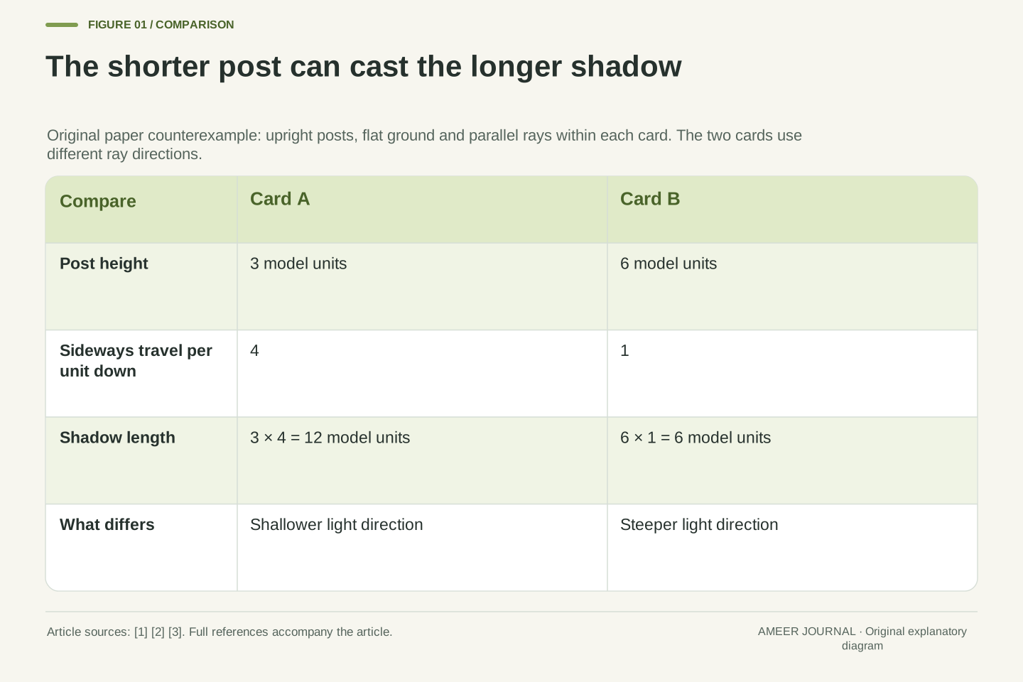
Here is the promised puzzle. Card A shows a three-unit post under a very shallow ray rule: four units sideways for each unit down. Its shadow is twelve units long. Card B shows a six-unit post under a steeper rule: one unit sideways for each unit down. Its shadow is six units long. Card A has the shorter post and the longer shadow. The numbers are consistent because the cards use different light directions.
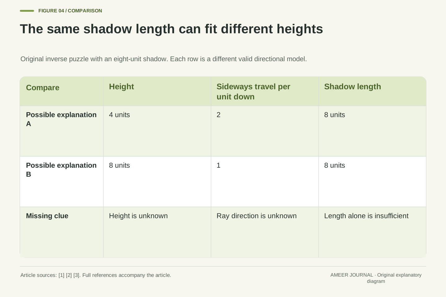
A longer shadow alone therefore cannot prove that an object is taller. The missing light information can change the answer. Try a second version with only an eight-unit shadow shown. It could belong to a four-unit post with the two-sideways rule. It could also belong to an eight-unit post with the one-sideways rule. Both fit that single shadow length. Asking for another clue is a complete scientific response, not a failure to solve the puzzle. You have found that the available information allows more than one explanation. The source material's dependence on relative light position is what makes this distinction necessary. [1][3]
The original counterexample assigns hA=3,kA=4, so LA=12, and hB=6,kB=1, so LB=6. Thus hA<hB while LA>LB. The ordering reversal directly disproves an unconditional implication from a longer shadow to a taller object. It does not contradict the equal-k proportional rule; that rule's premise is absent. Source geometry is part of the input required by the inference. [1][3]
The inverse problem is likewise underdetermined if only L is supplied. With L=8, both (h,k)=(4,2) and (8,1) satisfy L=kh. More generally, each positive candidate height can be paired with k=8/h in the ideal model. The examples establish non-uniqueness without requiring measurement noise or uncertain arithmetic. A child can identify the missing ray-direction clue in the Easy version; an adult can use the equation to see why that clue is structurally necessary. Supplying more digits for the shadow length would not resolve an independent unknown in the illumination geometry.
A known post can supply the missing comparison
A new card gives more information. A known post is two units tall and its shadow is three units long. An unknown post has a nine-unit shadow. The card states that both posts are upright on the same flat surface under the same parallel light direction. The unknown shadow is three times the known shadow, so the unknown post is three times as tall: six units. The known post supplies a comparison that the eight-unit-shadow puzzle did not have.
Check the result another way. The known post has one and a half shadow units for each height unit: three divided by two. A six-unit post under that same rule has nine shadow units. Both routes lead to the same answer. Now erase the sentence saying the light directions match. The six-unit conclusion is no longer guaranteed, because the two posts may use different rules. A reference is useful when it shares the conditions needed for the comparison. The number labels and the matching-geometry statement belong together; neither should quietly disappear when the answer is repeated.
Let the reference height be hr=2 and its shadow Lr=3, with an unknown object's shadow Lu=9. Under the shared positive k assumption, k=Lr/hr=3/2 and hu=Lu/k=6. Equivalently, hu=hr·Lu/Lr=2·9/3=6. These are two forms of the same similar-triangle relationship, using the common ray direction. The reference does not need to reveal an absolute source distance because the directional model contains no finite source location.
The relationship requires Lr>0. In the ideal directly-overhead limiting case, the horizontal extent of a thin upright post's shadow approaches zero for every height, and a zero-shadow ratio cannot identify height. The model also distinguishes a reference that matches the unknown's lighting from one observed under another direction. This is why the card explicitly supplies geometry rather than implying that any known post anywhere is a valid calibrator. The result is a deduction from stated quantities, not a recommendation to measure actual children, structures or outdoor shadows.
The reference calculation also separates a ratio from a length. Lu/Lr=9/3 is the dimensionless number three; multiplying it by hr restores a height in the reference's length unit. A sketch stretched differently in its horizontal and vertical directions would not justify reading k from its visual slant. In these cards, the numerical labels and equal-unit convention define the geometry.
A nearby light changes the rule
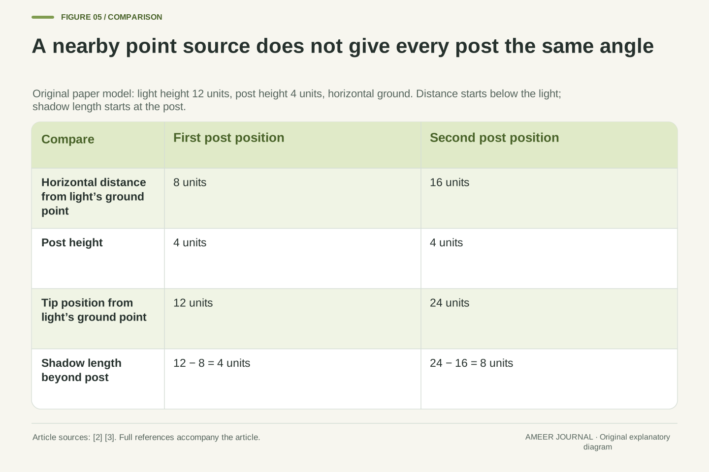
The next drawing replaces the parallel rays with a single nearby light dot. Imagine the dot twelve units above the ground. A four-unit post stands eight units sideways from the point directly below the light. The straight line from the light dot through the post's top continues down to the ground. It lands twelve units sideways from the light's ground point, so the shadow extends four units beyond the post's base. The distance to the tip and the length of the shadow are different numbers.
Move the same four-unit post to a position sixteen units sideways from the light's ground point, leaving the light dot fixed. The boundary ray now reaches the ground at twenty-four units, making an eight-unit shadow beyond the post. Its shadow doubled while its height stayed the same. Rays spreading from a nearby point reach the two positions at different angles. Sharing the same light dot is therefore not the same as sharing one parallel light direction. This is another original paper example of why source, object and surface positions must be considered together. [2][3]
Use a point source at (0,H), a post base at (D,0) and its top at (D,h), with H>h>0 and D>0. The line through source and post top intersects z=0 at x=HD/(H−h). Shadow length beyond the post base is therefore L=x−D=hD/(H−h). This original construction follows straight-line geometry; D is the horizontal separation from the source's ground projection, not the sloping source-to-post distance. [2][3]
For H=12,h=4,D=8, the ground intersection is x=12 and L=4. With only D changed to 16, x=24 and L=8. The effective top-ray factor is k=D/(H−h), which differs between the positions. It also depends on h for fixed H and D, so the parallel-ray height-ratio rule cannot simply be reused for two differently sized posts under a nearby source. The restrictions H>h and a horizontal receiving plane matter: the formula is not a general statement about all source positions. This example isolates divergence from a point source while continuing to ignore its physical size.
For the first point-source card, the boundary line drops eight units between the source and the post top while travelling eight units horizontally. It then drops the remaining four units over four more horizontal units. This checks the twelve-unit tip coordinate directly. Subtracting the eight-unit post position is essential: using the tip coordinate itself would count ground before the post as part of its shadow.
A fuzzy edge or a different surface needs another explanation
Our drawings have crisp tips because their rules make a sharp boundary easy to locate. A real light source can have noticeable size. Some parts of it may be blocked while other parts still light a region, making a softer edge. Other light can brighten the shadow, and a partly see-through object can let some light through. The Science Learning Hub transcript discusses these effects and distinguishes the darker central region from lighter edge regions. [3] A fuzzy edge is not, by itself, evidence that the object grew or shrank.
The receiving surface matters too. A shadow spreading across a wall is a projection onto that wall, while our length rule was built for a flat ground line. A leaning post also changes the drawing. Before using a new shadow to guess height, ask whether its geometry still matches the card you solved. You do not need to force every real-looking picture into the first rule. Models are tools for explaining selected features under stated conditions. Light basics notes that different models can help explain different aspects of light. [4] Here, the simple ray model makes a comparison clear, while its limits tell us when more information is needed.
Finite source extent can create locations where only part of the source is occluded, producing partial illumination rather than the ideal model's single sharp transition. The concept-map transcript discusses overlapping contributions, penumbral edges, diffraction and the influence of object-to-surface distance. [3] Our formulas describe geometric boundary rays for ideal directional or point illumination; they do not predict a measured edge threshold in a photograph. Indirect reflected light can further change brightness without changing the stipulated post height. [4]
Projection onto a different receiving plane is also a different geometric problem. Likewise, a nonvertical object's physical length need not equal the vertical h used in L=kh. These distinctions separate object dimensions, projected extent and visible contrast. More realistic modeling may be useful, but it must specify what is added rather than quietly applying the simple formula to new conditions. The educational use of a model is strongest when its assumptions stay inspectable. [2][4] For this paper activity, the correct response to an unmatched surface, unknown illumination or ambiguous edge can be to identify the missing condition before calculating.
Solve the last cards by asking what stayed the same
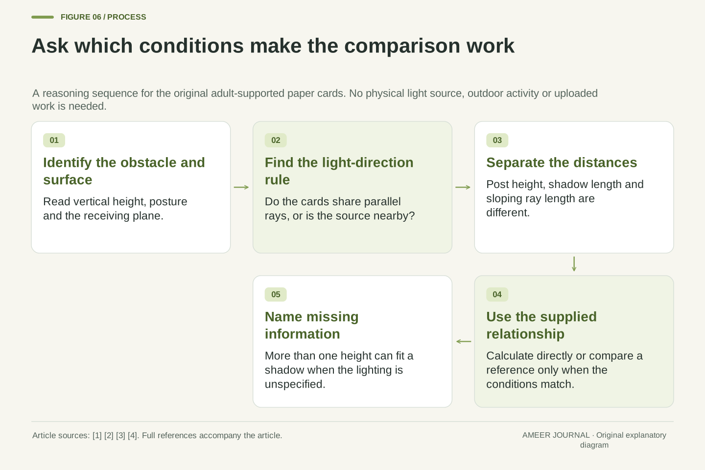
Try three final paper cards with a grown-up. Card One says the rays travel two units sideways for each unit down and the upright post is five units tall. The shadow is ten units long. Card Two shows an eight-unit shadow but leaves the light direction blank. Its height cannot be determined from that clue alone. Card Three gives a two-unit reference post with a three-unit shadow and an unknown post with a nine-unit shadow under the same parallel light and flat-surface rules. The unknown height is six units.
Explain why each answer is allowed. Card One gives both height and direction. Card Two leaves an independent clue missing. Card Three supplies a matched reference that lets the common direction cancel from the comparison. There is no score to submit and no need to share the page. The useful result is a sentence connecting evidence to a conclusion. A shadow can help compare heights when the relevant conditions match. Its length can also change because the light or receiving geometry changes. The careful question is not only “How long is it?” but also “Which object, light and surface produced this particular shadow?”
The closing cards restate three different inference tasks. For h=5,k=2, the forward calculation gives L=10. For L=8 with both h and k unknown, the inverse problem has multiple positive solutions. For hr=2,Lr=3,Lu=9 with matched geometry, the ratio gives hu=6. Each conclusion is tied to a different set of supplied quantities and assumptions. None is justified solely by observing that one dark shape looks long.
Across the activity, the governing distinctions are source versus obstacle versus receiving surface; height versus horizontal projection; common direction versus a nearby diverging source; and modeled boundary versus actual brightness transition. The original equal-height, reversed-order and point-source examples each change a different premise, so they should not be combined into an unqualified rule. The private paper discussion can stop at the Easy counting relationships or extend to the Technical equations with adult support. Its aim is an explanation that makes the missing information visible, without physical exposure, personal data or a claim that the drawings constitute an experiment.
Sources & further reading
Explore the references behind this guide. External pages may change after our review.
- Light and shadows — Science Learning HubScience Learning Hub / University of Waikato · Accessed 7 Nov 2026
- 1.1 The Propagation of Light - University Physics Volume 3 | OpenStaxOpenStax / Rice University · Accessed 7 Nov 2026
- Shadows: Effects of the absence of lightScience Learning Hub / University of Waikato, with New Zealand Ministry of Education text · Accessed 7 Nov 2026
- Light basics — Science Learning HubScience Learning Hub / University of Waikato · Accessed 7 Nov 2026
Article updated 7 Nov 2026.