What you’ll take away
- Equal full lengths do not imply equal gaps between supports.
- With the same centred point load and bending rigidity, midpoint deflection scales with the support span cubed.
- A support can hold its height while allowing the beam to turn there.
- An unloaded extension can rise; its movement need not share the midpoint’s comparison ratio.
- The invented beam calculation does not determine the safe load or failure behavior of real paper.
A bridge picture needs more than a long horizontal line
Imagine three paper drawings of a bridge. Each drawing shows the same long strip, but the little support marks sit in different places. Would the middles bend by the same amount? The strip’s full length is only part of the information. We also need the gap between its supports, the position of the downward load and the kind of movement being compared. Support conditions influence how a structure behaves [1][3]. A picture without those labels leaves the question unfinished.
Explore this puzzle with an adult on an uncut page. The activity is drawing, pointing and explaining; it does not involve building a bridge or balancing loads. The numbers describe an invented elastic beam, not a tested sheet of paper. There is no photograph, name or answer to upload. We will compare the downward movement of the middle, then discover why a free end can move in another direction. Naming the point being followed is just as useful as naming the support gap.
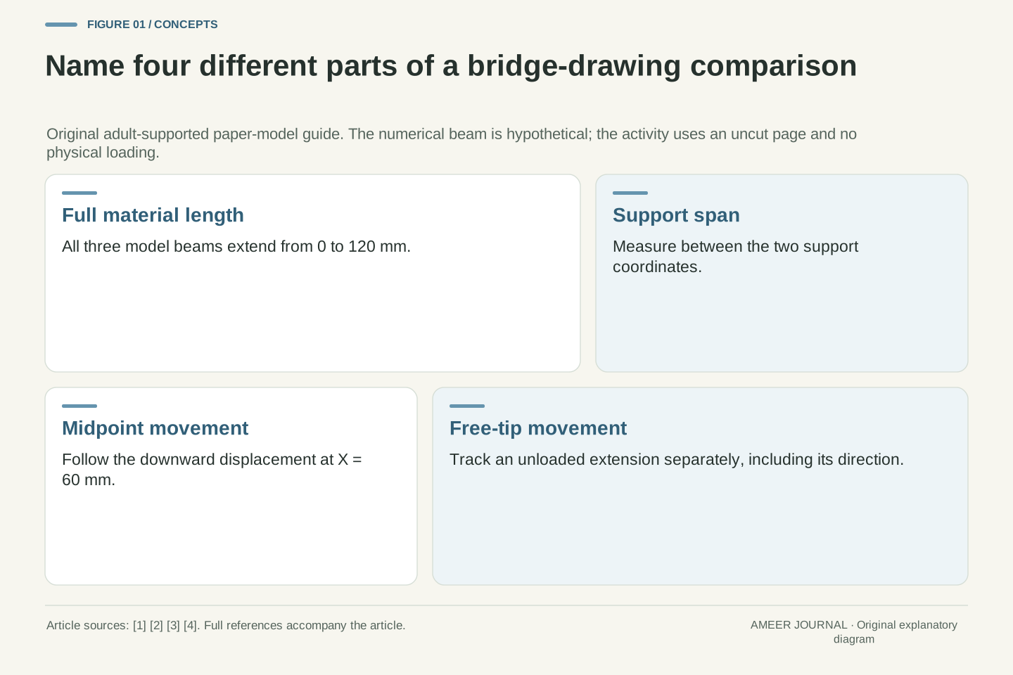
This adult-supported paper lesson separates four quantities: total material length, support span, midpoint deflection and displacement of an unloaded extension. The same total length does not determine the supported span, and a midpoint result does not automatically describe the largest absolute displacement of the complete object. Idealized support conditions are part of the mechanical model, rather than decorative details added to a drawing [1].
The original fixture is a uniform, slender, linear-elastic beam represented on an uncut page. It uses small-deflection Euler–Bernoulli bending, negligible beam weight and shear deformation, and a specified static point load. No axial or dynamic loading is present. The free extensions carry no applied load or end moment. These assumptions define an analytical example, not measured paper behavior or a load-capacity recommendation. All activity remains private and adult-supported: there is no physical construction, loading, cutting, photographing or data submission. Technical mode develops the same drawing relationships more precisely.
Keep the full length and the support gap separate
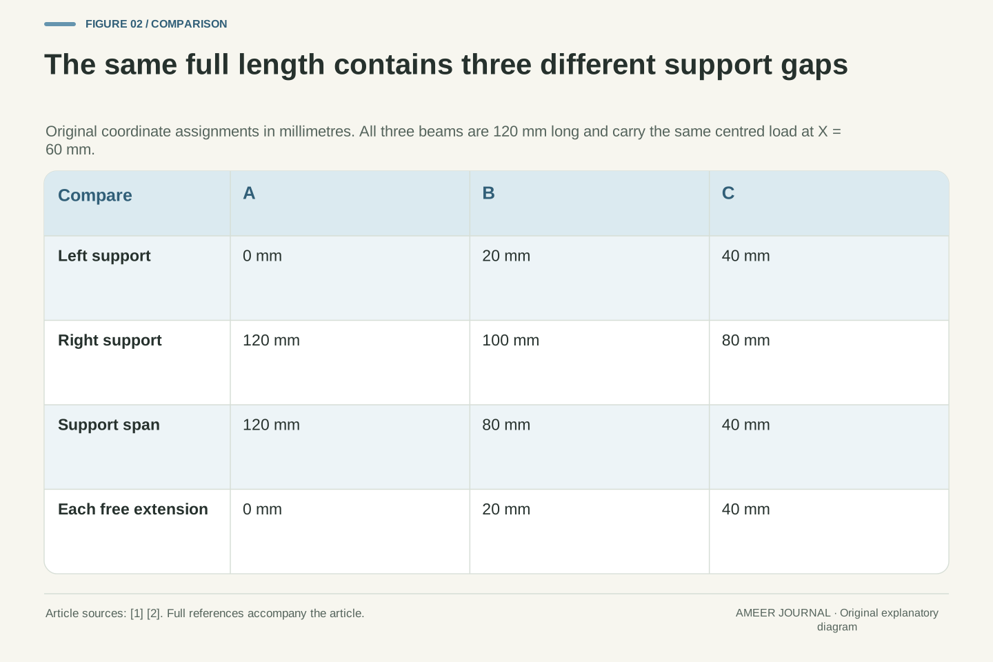
Give every drawn beam a left-end label of 0 and a right-end label of 120 millimetres. The labels define our model; the sketch need not be drawn exactly to scale. In drawing A, supports sit at 0 and 120. In B, they sit at 20 and 100. In C, they sit at 40 and 80. The support gaps are therefore 120, 80 and 40 millimetres. All three still contain the same total model length of 120 millimetres.
The portions outside the supports are called overhangs or extensions. B has 20 millimetres beyond each support, while C has 40. A has no extension beyond its supports. Moving the support marks has not cut any material away. MIT’s support guide explicitly allows supports at intermediate positions as well as at ends [1]. Trace the distance from one support to the other before reading a bending calculation. Tracing from the left end to the right end would answer a different question in B and C.
Use a global coordinate X measured in millimetres from the beam’s left end, with total length T=120 mm. Assign support pairs (a,b)=(0,120), (20,100) and (40,80) mm to A, B and C. Their spans L=b−a are 120, 80 and 40 mm. The symmetric unloaded extension length is h=(T−L)/2, giving 0, 20 and 40 mm on each side. These are original assigned dimensions, not observations.
Support locations need not coincide with material endpoints [1]. For the present load case, the bending formula will be applied to the supported interval a≤X≤b. The unloaded extensions remain attached and can inherit movement from that interval; they are not removed from the drawing or fixed flat by assumption. Keeping T, L and h distinct prevents substituting the same 120 mm into all three span calculations. The coordinate labels also make it possible to compare the same global midpoint, X=60 mm, across all three arrangements.
A support can hold a position while allowing a turn
Our two support marks have declared jobs. The left one is an ideal pin: it holds its position while allowing the beam to turn there. The right one is an ideal roller on a horizontal surface: it holds the vertical position while allowing a turn and horizontal movement [1]. These descriptions are rules for the drawing. They do not say that a real piece of paper resting on a household object will behave exactly that way.
A fixed or clamped end has a different rule: it also prevents the beam’s local turning motion [1][3]. A little curve near a freely turning support is therefore not evidence that the support has stopped working. Holding one point’s height and holding the beam’s angle are different constraints. Ask your partner to label our supports free to turn. That short phrase will matter later, when an unloaded extension rises even though the support point itself remains at its original height.
In the stated planar model, the pin restrains horizontal and vertical translation at the left support but supplies no reaction moment. The horizontal roller restrains vertical translation at the right support and supplies a vertical reaction; rotation and horizontal translation are permitted [1]. With only vertical applied loading, the pin’s horizontal reaction is zero. Both support-point transverse displacements are fixed at zero relative to their original positions.
A fixed boundary instead constrains displacement and slope and can supply a reaction moment [1][3]. Consequently, replacing the support symbols with clamps changes the boundary-value problem even if every length label stays the same. The pin/roller pair is an idealization selected for this lesson, not a description inferred from the appearance of a tabletop arrangement. In particular, a zero displacement at one support does not imply zero slope there. That distinction supplies the kinematic connection between the curved supported span and each straight, unloaded extension.
Follow the forces acting on the whole beam
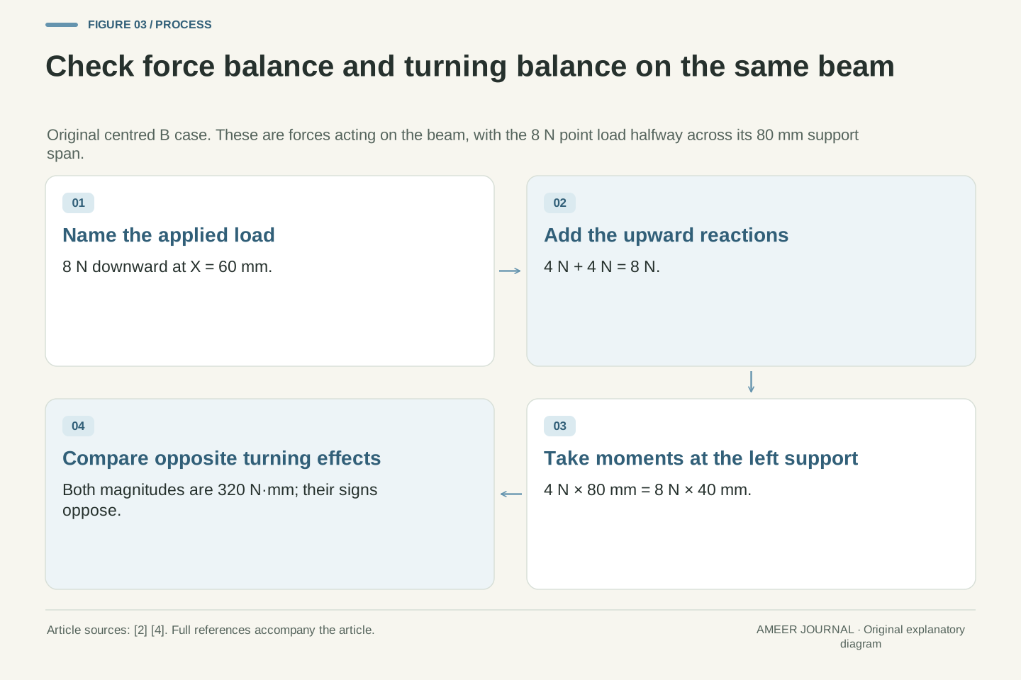
Place one downward arrow at the shared middle, the 60-millimetre mark, and label it 8 N. N means newtons, a unit of force. In our weightless model, the two supports together must provide 8 N upward. The middle lies equally far from the two supports in each drawing, so the upward reactions are 4 N on the left and 4 N on the right. Equal half-load reactions are the centred example described in the beam source [2].
Two checks belong together. The upward and downward forces must balance, and their turning effects must balance [4]. For B, the support gap is 80 mm and the load is 40 mm from either support. Taking moments about the left support compares 4×80 with 8×40; both give 320 N·mm. That product is a turning effect, not another force. Our arrows all describe forces on the beam. Mixing in the opposite forces that the beam exerts on its supports would mix different objects in one calculation.
Let the downward point-load magnitude be P=8 N at X=60 mm, and let R_a and R_b denote upward reactions on the entire beam. Vertical equilibrium gives R_a+R_b=P. Taking moments about the left support gives R_b L=P(60−a). Since 60−a=L/2 for A, B and C, R_b=P/2=4 N and R_a=4 N. The horizontal pin reaction is zero under the stated vertical loading [2][4].
For B, the right reaction produces 4 N×80 mm=320 N·mm about the left support, balancing the point load’s 8 N×40 mm=320 N·mm with opposite sign. These equal moments do not imply equal displacements or identify a material property. Static equilibrium fixes the support reactions in this determinate transverse-loading case; bending stiffness will enter the displacement calculation separately. All external forces in this free-body account act on the beam. The equal-and-opposite forces acting on the supports are not additional terms in the same beam equilibrium equation.
Balance does not tell us how much the middle moves
A beam can settle into a slightly bent shape while its external forces balance. The upward total of 8 N does not tell us whether the middle moved a tiny distance or a larger one. To predict that movement, our model also needs a measure of how strongly the material and cross-section resist bending. The beam formula combines those properties into a quantity we will call K [2]. We give all three drawings the same positive K.
Keeping K the same makes the support-gap comparison meaningful. If one drawing secretly used a different material or cross-section, a changed movement could have more than one explanation. Bending stiffness is also a different question from failure. A calculation of a small movement does not tell us when a real sheet creases, tears or slips at a support. Our puzzle supplies no failure threshold. Its question is narrower and answerable: how does the centre move in the same declared elastic model when the support marks move?
Write K=EI for the constant flexural rigidity, where E is Young’s modulus and I is the second moment of cross-sectional area about the relevant bending axis [2]. K has force-times-length-squared units. This area moment is not the rotational mass inertia also denoted I in mechanics texts. Keeping a separate symbol K makes the displacement equation easier to read without confusing geometric bending resistance with the rotational inertia appearing in the equilibrium source [4].
The analysis assumes linear material response, small deflections and a uniform slender beam; shear deformation and self-weight are neglected. Equilibrium alone supplies the reactions, while the curvature and displacement relations depend on K and the support constraints [2]. Identical P and K are therefore necessary conditions for the particular span-only comparison below. Neither K nor a calculated deflection is a failure load. The fixture supplies no constitutive failure limit, support-slip criterion or experimentally measured paper parameter, so those outcomes remain outside the calculation.
Doubling the support gap multiplies this centre movement by eight
For our freely turning supports and one load exactly halfway between them, the centre’s downward movement follows a cube rule: it is proportional to the support gap multiplied by itself three times, while the load and K stay fixed [2][3]. Doubling the gap therefore gives 2×2×2=8 times the centre movement. Tripling it gives 3×3×3=27 times the movement. The rule belongs to this particular centred point-load arrangement.
Compare the gaps with C’s 40 mm. B’s gap is twice as long, and A’s is three times as long. Their centre movements are therefore in the ratio A:B:C=27:8:1. If C’s centre movement is represented by one comparison unit, B needs eight and A needs twenty-seven. These are ratios, not measured millimetres. The full material lengths are equal, but the support gaps are not. We are also following the middle specifically; the ends of an overhanging beam will need their own calculation.
For a simply supported interval of span L with a central point load P, the downward midpoint-deflection magnitude is δ=P L³/(48K) [2]. The source’s short equation is retained directly from its native text. With the same positive P and K, ratios of δ equal ratios of L³. Thus δ_A/δ_C=(120/40)³=27 and δ_B/δ_C=(80/40)³=8. The point-load magnitude is held fixed; this is not an assertion about a fixed distributed-load intensity [3].
The maximum downward displacement within this symmetric supported interval occurs at its midpoint [2]. That local statement must not be enlarged into a claim about the largest absolute displacement anywhere on the complete beam, which also contains unloaded extensions in B and C. The supported-interval solution applies because those extensions have no applied forces or end moments and therefore contribute zero bending moment there. Their displacement follows from continuity of position and slope at the supports, rather than from an assumption that the extensions remain motionless.
Attach units to one fully specified calculation
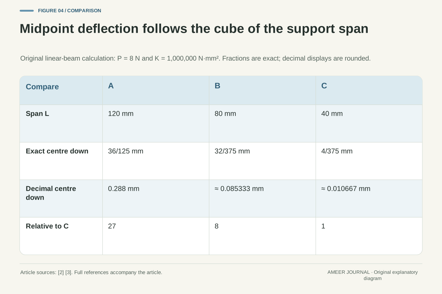
Now give our invented model a numerical K of 1,000,000 N·mm². This is an assigned calculation value, not a value measured from paper. Keep the downward arrow at 8 N. The model gives A’s middle a downward movement of 0.288 mm. B’s value is about 0.085333 mm, and C’s is about 0.010667 mm. The longer decimal results have been rounded; the comparison ratio remains exactly 27:8:1.
An adult can check B and C without treating the printed decimals as perfectly exact. C’s exact value is 4/375 mm and B’s is 32/375 mm, so dividing B by C gives eight. A is 36/125 mm, which is twenty-seven times 4/375 mm. These small model distances are labels for a calculation, not a request to measure a tiny bend at home. A drawing may exaggerate a curved shape to make it visible, so its apparent depth should not replace the stated numerical values.
Use millimetres throughout, with P=8 N and K=1,000,000 N·mm². Substituting L=120, 80 and 40 mm gives δ_A=36/125 mm=0.288 mm, δ_B=32/375 mm≈0.085333 mm and δ_C=4/375 mm≈0.010667 mm. The dimensional cancellation is (N·mm³)/(N·mm²)=mm. The fractions are exact within the declared model; the six-decimal displays are rounded.
These assigned values make the displacement calculation reproducible without assigning an elastic modulus or thickness to real paper. The ratios remain 27 and 8 because the common prefactor P/(48K) cancels. The corresponding point-load-to-midpoint-displacement stiffness P/δ is a property of each supported arrangement; it changes with L even though the material rigidity K is unchanged. Do not infer that moving supports has changed Young’s modulus. Likewise, an exaggerated schematic ordinate is not an additional measured value. Preserve the coordinate scale, units and displacement location when carrying the numbers into another representation.
Moving the arrow changes the support shares
Keep B’s supports at 20 and 100 mm, but move the downward 8 N arrow from 60 to 40 mm. It is now 20 mm from the left support and 60 mm from the right. The support shares become 6 N upward on the left and 2 N on the right. They still add to 8 N. The closer support carries the larger share in this specific two-support example.
Check the turning effects about the left support. The right support contributes 2×80=160 N·mm, and the downward arrow contributes 8×20=160 N·mm in the opposite direction. Both balance conditions now agree [4]. Keeping 4 N on each support would balance the force total but fail the turning check. The central-load bending rule cannot simply follow the arrow to its new position. The source treats a point load at a general position as a different calculation [2]; our earlier centre numbers belonged to the centred arrow.
For an original off-centre variant of B, keep a=20 mm and b=100 mm but set X_load=40 mm. Moment equilibrium gives R_b=P(X_load−a)/L=8×20/80=2 N; force equilibrium then gives R_a=6 N. The moments about the left support both have magnitude 160 N·mm. Mirroring the load to X=80 mm reverses the reaction pair to 2 N and 6 N [4].
The equal-reaction result for A, B and C depended on their centred loading, not merely on there being two support symbols. The off-centre variant also has a different deflection field. Roylance gives the general-position point-load expression separately from the central case [2]. No off-centre deflection or maximum-location value is calculated here. In particular, substituting the unchanged 80 mm span into P L³/(48K) would silently restore the missing central-load assumption. Preserve the global load coordinate and its two support-relative distances alongside the reaction values.
An unloaded end can rise while the middle moves down
Return the arrow to the centre. B and C still have unloaded extensions beyond their supports. Unloaded means that our model puts no extra force or end moment on those extensions. It does not mean that the extensions must stay at their old height. The beam is allowed to turn at each support. A straight extension follows that turn, so its free tip rises while the middle of the supported part moves down [1][2].
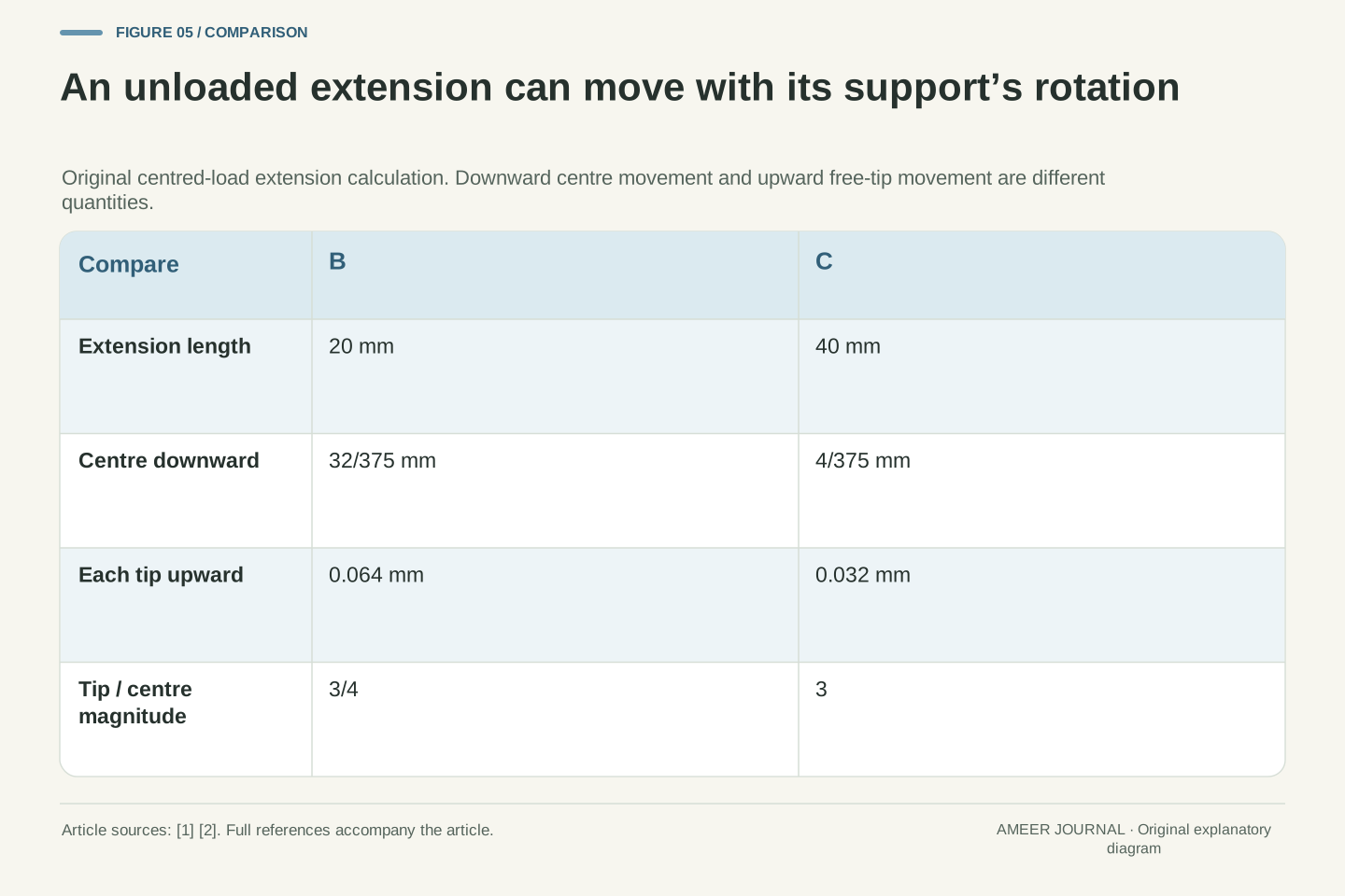
The model gives B an upward free-tip movement of 0.064 mm and C an upward movement of 0.032 mm. B’s upward tip movement is twice C’s, even though its downward centre movement is eight times C’s. For C, the tip moves upward three times as far as the centre moves downward. There is no contradiction: these are different locations and directions. A sentence saying the middle moves least does not automatically describe every other point. Keep centre down and free tip up as separate entries when comparing the drawings.
For the left half of a supported interval, take downward displacement positive and use local coordinate u=X−a. The central-load solution is w(u)=P u(3L²−4u²)/(48K). Differentiation gives support-slope magnitude θ=P L²/(16K). A free, unloaded extension has zero moment and curvature in this model, so its straight continuation inherits that slope. At a left extension of length h, w_tip=−hθ; the negative sign denotes upward movement. Symmetry gives the same upward magnitude at the right tip [2].
For B, θ=0.0032 and h=20 mm, giving 0.064 mm upward. For C, θ=0.0008 and h=40 mm, giving 0.032 mm upward. Their tip-to-centre magnitude ratios are 3h/L: three quarters for B and three for C. Thus B/C is eight for midpoint downward displacement but two for upward tip displacement. C’s tip magnitude exceeds its midpoint value. This is why the centre cannot be called the complete beam’s largest absolute movement merely by importing the simply supported interval statement.
Change one rule and check which comparison survives
Suppose we keep B’s span and central arrow but double its assigned K. The model’s centre movement becomes half as large because the bending formula divides by K [2]. The support shares remain 4 N and 4 N: the same centred 8 N arrow still needs the same force and turning balance. This separates two questions that can look similar in a picture—how the supports share the force, and how much the beam bends.
Other changes need different care. A clamp prevents turning that our pin and roller allow. A load spread along the beam is different from our one arrow. Extra weight on an extension would remove the unloaded-extension assumption [1][2][3]. Before carrying a result to another drawing, compare the labels that produced it. Do not treat the numerical K or the calculated movements as a safe loading guide for real paper. The puzzle has described elastic movement and has supplied no information about failure, slipping or permanent creases.
Doubling K for the centred B configuration gives δ_B,new=16/375 mm, exactly half its previous midpoint deflection. The statically determinate reactions remain 4 N each. The distinction is between unchanged external equilibrium and changed elastic response. The source’s linear displacement treatment supports proportional changes within its fixed geometry and boundary assumptions [2]; it does not imply that every physical material remains linear at arbitrary loads.
Changing support type, loading position or load distribution changes the applicable problem rather than merely changing a number in the existing answer. Fixed boundaries constrain slope; an applied extension load contributes additional internal forces and moments; distributed loading needs its own spatial description [1][2][3]. The area moment and material modulus would also need reevaluation for a different cross-section or material. None of these substitutions is a claim about a real paper bridge’s safe load. Stiffness, a particular displacement and failure capacity require different information, and only the first two are specified in the present ideal example.
Repair four captions with your reading partner
Try a caption-repair game on the same page. First read: “The three beams have equal full lengths, so their middles move equally.” Replace the part after so with the support-gap comparison: their gaps are 120, 80 and 40 mm, and their centre movements have ratio 27:8:1 under the stated rules. Next read: “An unloaded extension cannot move.” Repair it by explaining that the extension can rise with the beam’s turn at its support.
The third caption says: “Moving B’s arrow to 40 mm leaves 4 N at each support.” Replace those values with 6 N on the left and 2 N on the right, then point to the distances used in the turning check. The last caption says: “The table tells us the safe load for a real paper bridge.” Explain which information is absent instead of supplying a guessed load. An adult can listen to your reasoning. The aim is to improve the sentence, with no score or personal details recorded.
The four original captions test different inference boundaries. Equal total lengths do not establish equal spans; zero applied loading on an extension does not impose zero displacement; equal reaction shares do not survive an off-centre point load; and a displacement fixture does not supply a real failure criterion. The corrections should identify the specific premise that the original sentence omitted, rather than replace it with another universal rule.
For the first caption, retain the common P, K and central-loading assumptions when giving 27:8:1. For the second, distinguish zero curvature from zero slope and translation. For the third, cite the 20 mm load arm and 80 mm support span in the 6/2 N reaction calculation. For the fourth, state that neither real-paper properties nor a safe-load boundary has been established. This is a private explanation exercise, not a survey, model prediction about children or assessment dataset. The partner’s role is to ask which label or equation justifies each correction.
Write a caption that says what moved and why
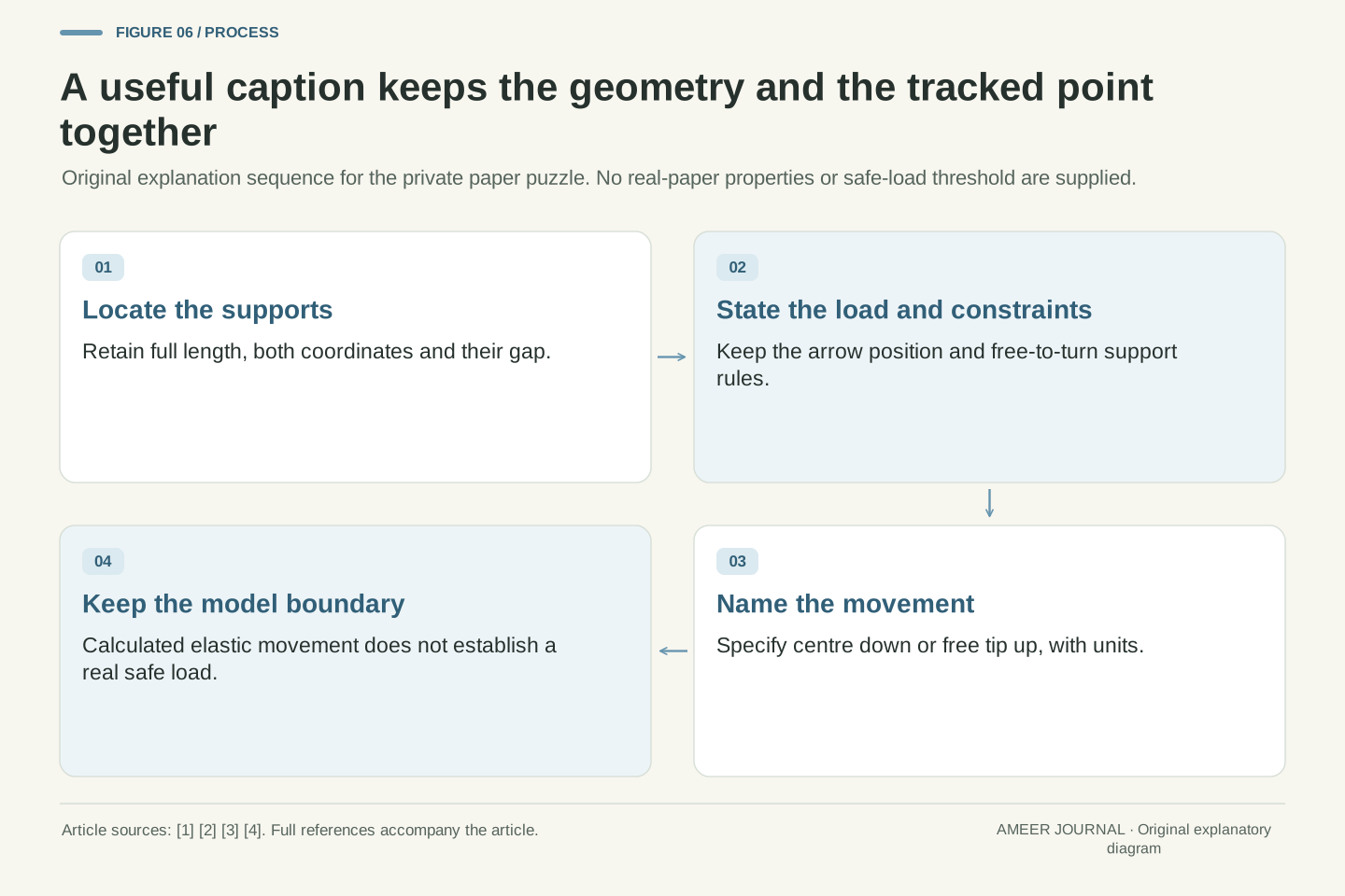
A complete caption can begin with the full length and the support positions. Then name the arrow’s position and the movement being followed. For example: “B has a 120 mm model length, supports at 20 and 100 mm, and an 8 N downward arrow at 60 mm. Under the stated elastic rules, its middle moves downward eight times as far as C’s middle.” The word middle prevents that sentence from quietly becoming a claim about every point.
Add a second sentence if you are discussing the tips: “B’s unloaded tips move upward 0.064 mm, while C’s move upward 0.032 mm in this model.” Your partner can now tell which locations and directions the numbers describe. The support marks, their turning rules and the load labels all helped explain the result. A useful paper bridge puzzle is therefore more than choosing the longest line. It is an opportunity to read the whole set of drawing rules and make the comparison those rules actually support.
A reproducible caption preserves T, the support pair, the load magnitude and location, K, the support constraints and the displacement coordinate. For B, those are T=120 mm, (a,b)=(20,100) mm, P=8 N at X=60 mm and K=1,000,000 N·mm², with a pin and a horizontal roller. The midpoint downward value is 32/375 mm; the separate free-tip upward magnitude is 8/125 mm. Each result has a location, direction and explicit model boundary.
The complete comparison is therefore not a single ranking called bending. It contains midpoint ratios, extension movements and support reactions that answer different questions. The same material length can have different support spans, and the same supported span can respond differently when its load or constraints change [1][2][3]. The original paper exercise supplies enough information for its chosen calculations while leaving real-material failure and construction performance unclaimed. A clear caption makes those boundaries visible without asking the reader to guess which part of the drawing the author meant.
Sources & further reading
Explore the references behind this guide. External pages may change after our review.
- Lecture 13: SupportsMassachusetts Institute of Technology / Chris H. Luebkeman and Donald Peting · Accessed 7 Nov 2026
- 4.3: Beam DisplacementsDavid Roylance / Massachusetts Institute of Technology via Engineering LibreTexts · Accessed 7 Nov 2026
- Span and DeflectionUniversity of Manchester — Seeing and Touching Structural Concepts · Accessed 7 Nov 2026
- 12.1 Conditions for Static Equilibrium - University Physics Volume 1 | OpenStaxOpenStax / Rice University · Accessed 7 Nov 2026
Article updated 7 Nov 2026.