What you’ll take away
- A steady glide has air-relative and ground-relative motion; wind links the two descriptions.
- L/D equals horizontal air travel per height in the stated steady glide, not every ground-distance ratio.
- The glide ratio does not by itself determine duration, so wind drift needs a time or rate input.
- Sideways drift can increase horizontal ground-track length without increasing forward progress.
- Two invented states show that a larger L/D can still give less forward ground reach in a stated headwind.
- Read and draw with an adult on screen or uncut paper; no launches, outdoor trials, uploads or personal details are needed.
A glider can follow one air path and a different ground path
Imagine a little glider drawn above a ground line. It moves forward through the air while gradually descending. Now imagine that the whole surrounding air moves sideways or along the ground. The glider's movement through that air and its movement past a mark on the ground are different descriptions of the same journey [4][6].
That difference matters when someone says a glider travels four metres forward for every metre it drops. Which forward distance do they mean? In still air, the air and ground descriptions agree. With wind, the numbers can separate. We will follow an invented glider through a few exact drawings, then explain why a longer ground journey does not automatically mean better aerodynamics.
This is a private drawing lesson to read with an adult or suitable learning partner. Use the screen or an uncut sheet of paper. No folding, throwing, climbing, outdoor trial or actual aircraft is needed. All distances and speeds below are chosen for the explanation, not measurements or performance promises for a paper aeroplane.
A steady unpowered glide has an air-relative trajectory and a ground-relative trajectory. Uniform translational wind changes the latter without requiring a change to the stipulated air-relative velocity. The relevant transformation adds the velocity of the air relative to the ground to the velocity of the glider relative to the air [4][6].
Our original model uses straight constant-velocity descent, uniform horizontal wind, no thrust, no vertical air motion and no steering adjustment. We start after any launch transient. The same specified air-relative operating state is compared across winds; we are not claiming that a real free-flight model instantly acquires that state after a gust or release.
This adult-supported Kids lesson uses only diagrams on screen or uncut paper. There is no physical launch, equipment, altitude access, data collection or online submission. Technical mode develops the force geometry and vector arithmetic for a learning partner. All numerical fixtures are hypothetical; they neither measure a paper design nor provide a flight-navigation procedure.
Label air motion and ground motion before adding numbers
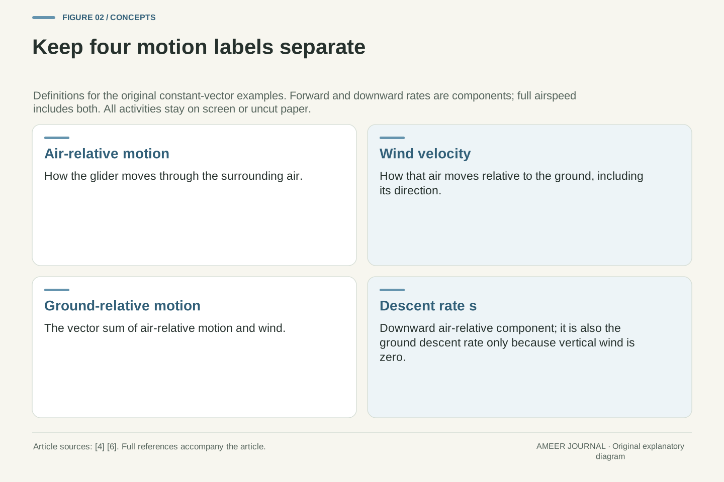
Give the drawing a forward arrow pointing right. A metre per second means one metre of travel during each second. Our main glider, A, moves four metres forward through the air each second and one metre downward each second. Those are two parts of its motion, rather than two competing descriptions of its total speed.
Wind describes how the air moves past the ground [4]. A wind arrow pointing right adds rightward ground motion. One pointing left subtracts it. A sideways wind needs its own arrow; its size cannot simply be added to the forward number. OpenStax explains this combination using velocity vectors, quantities that retain direction as well as size [6].
Use three labels: glider through air, air over ground, and glider over ground. The first arrow plus the second gives the third. None is the angle of the glider's nose in a photograph. We are tracking motion directions, so the drawn forward arrow should be labelled air-relative travel rather than treated as a complete description of the aircraft's shape.
Choose forward x, sideways y and upward z axes fixed to the ground. Define glider velocity relative to air as v_air=(u,0,−s), where u>0 is its horizontal forward component and s>0 is its descent rate. Define wind velocity w=(w_x,w_y,0). Then v_ground=v_air+w=(u+w_x,w_y,−s) [4][6].
The full airspeed magnitude is √(u²+s²), not u alone. Likewise the horizontal ground-speed magnitude is √((u+w_x)²+w_y²), distinct from the signed forward component u+w_x. Retaining these names prevents a sideward contribution from being mislabeled forward progress. Our signs describe the direction air moves toward; a positive w_x is a tailwind component.
For A, u=4 m/s and s=1 m/s, so the airspeed magnitude is √17 m/s. Its air-relative trajectory is fixed by these components. A body-axis orientation or angle of attack is not specified by that trajectory alone. The model assumes an available steady operating state rather than deriving one from an unmeasured folded-paper geometry.
Balanced forces can accompany a steady descent
A steady glide is not motion with no forces. Weight acts downward, while air supplies lift and drag. Lift is perpendicular to the glider's motion through the air, and drag opposes that motion [3][4]. In a descending glide, lift therefore does not point exactly straight up, and drag has an upward part.
The three forces can balance while the glider keeps moving at a constant velocity. No overall force means no change of velocity, not no movement. NASA's glider explanation uses that balance to relate the glide angle to lift divided by drag, usually written L/D [2][3]. A larger ratio corresponds to a shallower steady air-relative descent.
For our model A, the forward-to-downward motion ratio is four to one. The matching steady L/D ratio is four. This does not mean lift alone equals weight, or that the glider has an engine pulling it forward. It identifies the geometry of the chosen balanced glide. The later wind examples keep that air-relative geometry fixed.
Let γ be the downward air-relative trajectory angle from horizontal, with 0<γ<90°. Resolve the steady unpowered forces in the vertical and forward directions: L cos γ+D sin γ=W and L sin γ−D cos γ=0 [3]. Here L and D are magnitudes defined relative to air motion; W is the weight magnitude.
The horizontal balance gives D/L=tan γ=s/u. Combining the two balances also gives L=W cos γ and D=W sin γ. Thus L/D=u/s exactly for this model. We do not replace tan γ by γ, invoke a small-angle approximation or use the level-flight statement L=W in a descending glide.
A constant horizontal translation between the air and ground frames preserves acceleration [6]. The stipulated zero-acceleration air-relative state is consequently also constant-velocity ground motion. This is why adding uniform wind to the model is consistent with the same force balance. It does not establish that accelerating or spatially varying air leaves the aircraft's operating state unchanged.
Separate horizontal reach from the sloping path
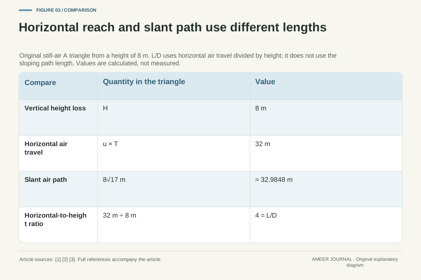
Start the drawn glider eight metres above its finishing level. At one metre of descent each second, it takes eight seconds to lose that height. During those eight seconds it moves four times eight, or 32 metres, horizontally through the air. In still air, that is also its horizontal ground travel.
Draw a right triangle with a vertical side of eight units and a horizontal side of 32 units. The sloping side is the glider's air-relative path. It is slightly longer than 32 units, because it includes the downward movement too. The ratio four comes from horizontal distance divided by height, not from that sloping length [1][2].
The downward angle is about 14.04 degrees. You do not need to measure that angle on your page to use the example: the chosen forward and downward numbers already define it. A sketch that is not drawn to scale can still carry correct labels. Keep those labels beside the correct sides so the picture does not silently change which distance is being counted.
For initial height H=8 m and constant s=1 m/s, descent time is T=H/s=8 s. Air-relative horizontal displacement is X_air=uT=32 m, giving X_air/H=u/s=4=L/D. This is the exact horizontal geometry used in the stated steady, still-air interpretation of the NASA glide relations [1][2].
The slant air-relative path length is T√(u²+s²)=8√17 m≈32.9848 m. Dividing that length by H gives √17≈4.1231, which is not L/D. The angle satisfies γ=arctan(1/4)≈14.0362°. These numbers distinguish horizontal displacement, vertical loss and three-dimensional path length rather than treating all of them as a generic flight distance.
All values are conditional on the declared constant components and level finishing plane. The drawing coordinates need not be metres on the page; its labels represent the hypothetical physical units. Scaling both illustrated sides by the same factor preserves the angle, while replacing the horizontal leg by the hypotenuse changes the ratio's meaning.
The same glide ratio can leave different time for the wind
The ratio four does not tell us how many seconds the glide lasts. Consider a separate invented state, C, with eight metres of forward air motion and two metres of descent each second. It also moves four metres forward for each metre downward. From eight metres up, however, it reaches the finishing level in four seconds.
A and C both cover 32 horizontal metres through the air. A takes eight seconds and C takes four. Add a constant rightward wind of one metre per second. During A's journey, the air shifts eight metres over the ground; during C's, it shifts four. Their forward ground displacements are therefore 40 and 36 metres.
We have kept the glide ratio equal while changing the rates. This is a constructed comparison, not a claim that one actual paper design can choose either state. It shows why the ratio alone cannot supply a wind-drift number. You also need the time aloft, or enough information to calculate it.
The ratio R=u/s constrains a direction but not the magnitudes of u and s. Define C separately by u_C=8 m/s and s_C=2 m/s. It shares R=4 with A but has T_C=H/s_C=4 s and full airspeed 2√17 m/s. Both states have X_air=RH=32 m.
For constant along-track wind, X_ground=(u+w_x)H/s=RH+w_xT. With w_x=1 m/s, A yields 32+8=40 m and C yields 32+4=36 m. The additional term is a displacement: wind velocity multiplied by duration. It cannot be reconstructed from a dimensionless glide ratio and height without a time or rate input [5][6].
This pair isolates underdetermination in the information supplied. It does not specify a lift/drag polar or prove that both states occur for the same vehicle, mass or density. Treat them as distinct hypothetical steady states. Equality of geometric ratios is sufficient for equal still-air horizontal reach from H, but insufficient for equal wind displacement.
Add the air’s movement during the eight-second descent
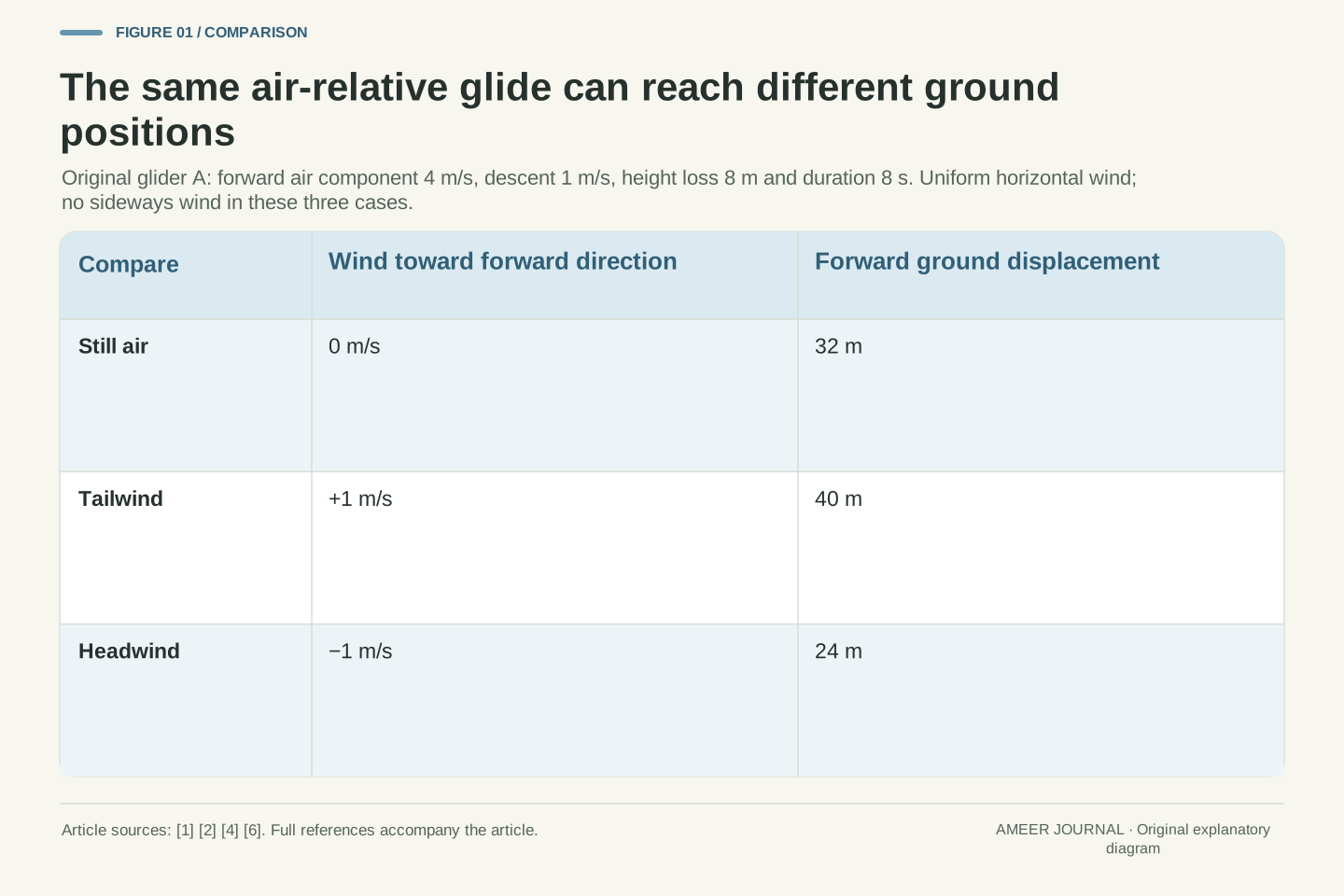
Return to A: four metres forward through the air each second, one metre down, and eight seconds aloft. With a rightward wind of one metre per second, it moves five metres forward over the ground each second. Five times eight gives 40 metres of forward ground travel.
With an equally strong leftward wind, its forward ground rate is four minus one, or three metres per second. Three times eight gives 24 metres. The air-relative horizontal travel remains 32 metres in both cases. Wind has added or subtracted eight metres of ground displacement during the same eight-second interval [4][5][6].
The ground triangles now have different horizontal sides but the same eight-metre drop. Their forward-ground-distance-to-height ratios are five and three. Neither changes A's L/D of four. A ground-view photograph or distance label needs its wind context before it can be used to describe the aerodynamic glide ratio.
For A with w_y=0, X_ground=(4 m/s+w_x)(8 s). The cases w_x=0,+1,−1 give forward velocities 4,5,3 m/s and displacements 32,40,24 m respectively. In all three cases v_air=(4,0,−1) m/s and T=8 s remain fixed.
The forward ground descent angles, while u+w_x>0, satisfy tan γ_ground=s/(u+w_x). Thus their tangents are 1/4,1/5 and 1/3, whereas the air-relative tangent remains 1/4. The still-air equality between horizontal ground distance divided by height and L/D cannot be transferred unchanged into the wind cases [2][4][6].
This is a reference-frame comparison under prescribed motion, not an assertion that wind changes no aerodynamic variable in every real flight. We have explicitly held the air-relative state fixed and excluded gusts. All three ground trajectories are straight, so their positive forward displacements also equal their horizontal ground-track lengths in these aligned cases.
Zero forward ground progress does not mean zero air motion
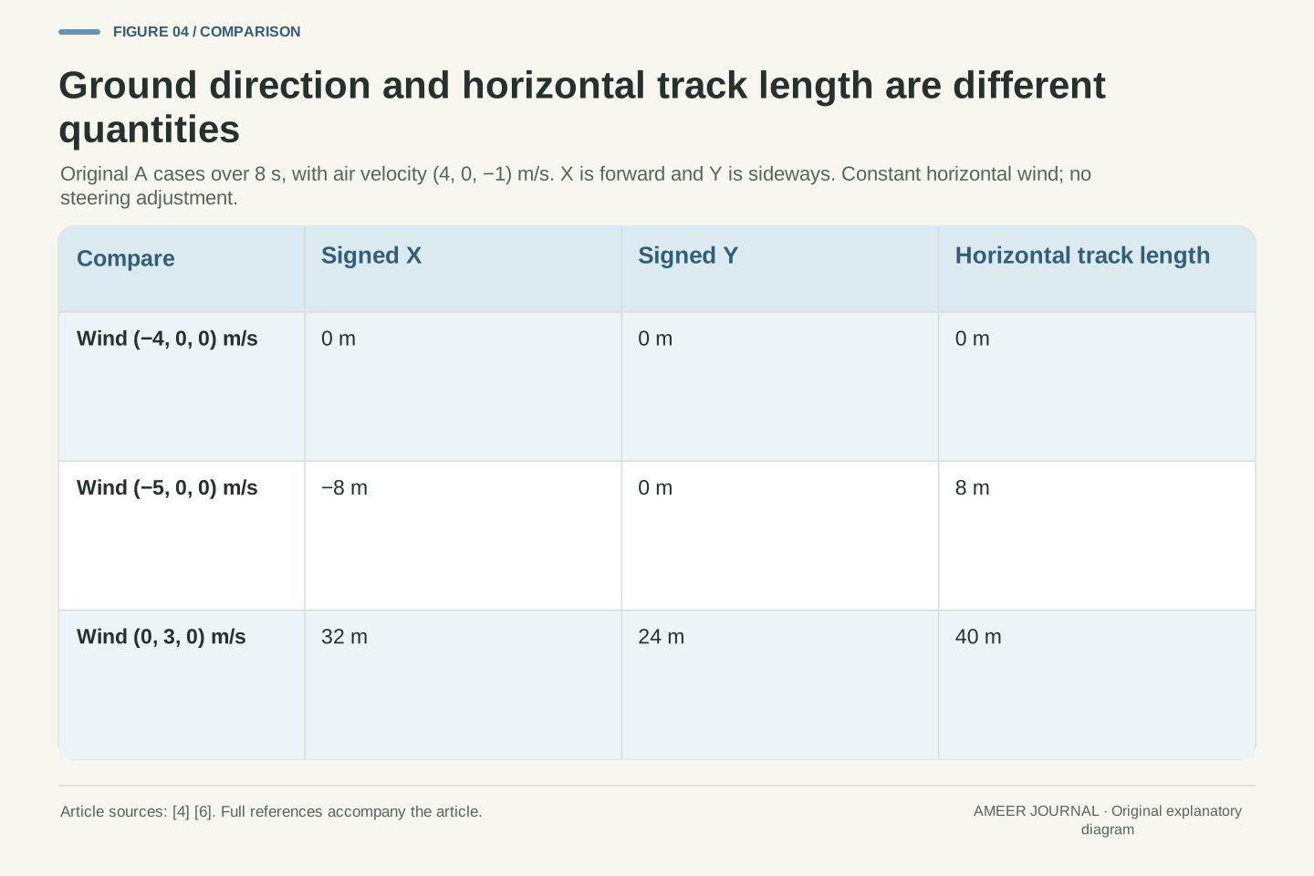
Imagine a stronger leftward wind: four metres per second. A still moves four metres forward through the air each second. These horizontal motions cancel in the ground view. Its forward position stays over the same ground mark as it descends through eight metres in eight seconds.
The glider has not stopped relative to the air. Its airspeed and the chosen steady force balance remain the same. Now change the leftward wind to five metres per second. Its forward ground rate becomes minus one metre per second, so it finishes eight metres to the left of the starting ground mark.
The minus sign records direction. It does not mean a negative amount of travelled path or a reversed flow in the glider's air frame. The horizontal ground-track length is eight metres in that last straight case, while the signed forward displacement is minus eight. A good drawing keeps both the direction arrow and the quantity's name.
For w_x=−u=−4 m/s, the ground velocity is (0,0,−1) m/s. The horizontal ground displacement is zero but the air-relative velocity remains (4,0,−1) m/s. The ground trajectory is vertical; the formula s/(u+w_x) has a zero denominator and must not be reported as an ordinary finite tangent ratio.
For w_x=−5 m/s, ground velocity becomes (−1,0,−1) m/s, with signed X_ground=−8 m. The horizontal track length is |X_ground|=8 m, whereas the three-dimensional ground path is longer. Our air-relative lift and drag directions have not reversed: a change in ground-referenced progression does not redefine the aerodynamic reference frame [4][6].
These limit cases also expose the danger of using signed advance as an unsigned range. The identity X_ground/H=R+w_x/s remains algebraically valid, including zero and negative results, but its left side then describes signed forward displacement per height. Neither a zero nor a negative value is the glider's positive L/D magnitude.
A longer ground track can include sideways travel
Now give A no along-track wind, but let the air move sideways at three metres per second. Keep its air-relative travel arrow pointing in the original forward direction. After eight seconds it is 32 metres forward and 24 metres sideways from its starting ground point.
In a top-down drawing, those two displacements form the legs of a right triangle. Its diagonal is 40 metres. That is the horizontal ground-track length in this constant straight case, while the progress in the originally chosen forward direction is still 32 metres. Adding 32 and 24 would count a two-part corner route that the glider did not follow.
The ratio 40 divided by eight is five, even though the air-relative glide ratio is still four. The extra horizontal track includes sideward drift. We have not turned the air-relative travel arrow to compensate for that drift. This comparison is about reading two labelled directions, not about steering a real aircraft.
Set w=(0,3,0) m/s while retaining A's v_air=(4,0,−1) m/s. Then v_ground=(4,3,−1) m/s. Over T=8 s the horizontal displacement is (32,24) m, with magnitude √(32²+24²)=40 m. Forward progress is its x component, 32 m, not its magnitude or the sum of coordinate lengths.
The horizontal track angle relative to the selected forward axis is arctan(3/4)≈36.8699°. Its horizontal speed is 5 m/s. Ground horizontal distance divided by height is therefore 5, distinct from L/D=4. This follows vector addition and geometry; the crosswind is not inserted as an extra scalar forward speed [6].
The air-relative direction is held fixed, so no heading compensation or turn is modeled. Because both horizontal components are constant, displacement magnitude equals horizontal path length here. That equality would require a new check for a curved route. The vertical component remains −1 m/s because the stipulated wind has no vertical component.
A larger L/D need not win a ground-distance comparison
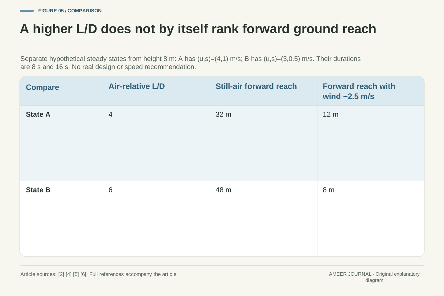
Compare A with a different invented glider state, B. B moves three metres forward through the air each second and drops half a metre each second. Its forward-to-downward ratio is six, better than A's four for still-air horizontal reach. From eight metres up, B stays aloft for 16 seconds and covers 48 horizontal metres through the air.
Add the same leftward wind of two metres per second to both. A makes two metres of forward ground progress each second for eight seconds: 16 metres. B makes one metre each second for 16 seconds: also 16 metres. Their different glide ratios now produce equal forward ground displacement.
With a leftward wind of two and a half metres per second, A advances 12 metres and B advances eight. B still has the larger L/D, but its longer duration allows more backward wind drift. This is an exact comparison of the stated fictional states, not a recommendation about which real plane, fold or flying speed to choose.
Define B independently by u_B=3 m/s, s_B=1/2 m/s, R_B=6 and H=8 m. Then T_B=16 s and X_air,B=48 m. A has R_A=4, T_A=8 s and X_air,A=32 m. The same constant along-track wind w_x applies to both stated operating states.
Their forward ground displacements are X_A=32 m+(8 s)w_x and X_B=48 m+(16 s)w_x. Hence X_B−X_A=16 m+(8 s)w_x. Equality occurs at w_x=−2 m/s. At −5/2 m/s, X_A=12 m and X_B=8 m, while both forward ground velocities remain positive.
The reversal is caused by the separate duration-dependent wind terms. It does not establish a speed-to-fly rule: no common aircraft polar, allowable control family, stability model or changing weather is supplied. It is a counterexample to inferring a ground-distance ranking solely from L/D. Under still air the ratio-based ranking in this exact fixed-height model remains correct.
The same ground record can hide different air paths
Suppose a drawing record says only: eight metres of height lost, 40 metres of forward ground travel, and eight seconds elapsed. Does that establish a glide ratio of five? Our A example with a one-metre-per-second tailwind already matches all three recorded numbers while keeping an air-relative ratio of four.
Another invented state could move five metres forward and one metre down through still air each second. It would also finish 40 ground metres forward after eight seconds, but its glide ratio would be five. Even the extra time label does not settle the difference if the air's motion is unknown.
If the record also supplies a trustworthy constant wind, subtract its displacement during the interval from the ground displacement. For A, 40 minus one times eight gives 32 metres of air-relative horizontal travel. Then 32 divided by eight recovers four. The missing information is the wind record, not a cleverer name for the same ground distance.
Construct two records with identical H=8 m, T=8 s and X_ground=40 m. Record one is A with u=4, s=1 and w_x=1 m/s, giving R=4. Record two has u=5, s=1 and w_x=0, giving R=5. Both have zero sideways wind and the same ground velocity (5,0,−1) m/s.
Ground endpoint and duration therefore do not uniquely identify the air-relative ratio when wind is unknown. Under the declared constant horizontal-wind and straight-steady assumptions, X_air=X_ground−w_xT, followed by R=X_air/H. For record one this gives (40−1×8)/8=4. A vector form similarly subtracts wT from ground displacement [6].
This inversion presumes the wind describes the relevant air throughout the interval and that the chosen model applies. It is not an instruction to estimate real aerodynamics from a casual outdoor observation. The two constructed histories establish an information limit: identical ground records can coexist with different air-relative states unless an additional frame relation is supplied.
Keep the steady-glide promise within its stated conditions
Every example kept the air moving at one constant horizontal velocity. A rising or sinking air current would change how quickly the glider loses height relative to the ground. A changing wind could also make the simple straight-path drawing insufficient. Those are different problems from adding the constant arrows used here.
We also began with a steady glide already established. A real paper plane can be in a launch, turn or other changing part of its motion, so its start-to-finish journey need not match our eight-second triangle. NASA explicitly introduces its glide geometry under constant velocity and no acceleration [1]. Those conditions are part of the explanation, not optional small print.
The drawings therefore cannot rank real paper designs, infer a complete flight from a folding pattern or guarantee where something lands. They can explain what a distance claim means. Ask which frame supplied the distance, whether sideways travel is included, how long the interval lasted and what wind was stated. Those questions make the arithmetic useful.
The duration T=H/s uses w_z=0. If a nonzero constant vertical wind were introduced, ground vertical velocity would be −s+w_z, and the ground descent rate would differ from s. We do not extend the present results to that case. Spatial gradients, time-dependent wind and changing attitude likewise fall outside the fixed-vector fixture.
Steady force balance and constant trajectory are assumptions, not conclusions drawn from a paper design [1][3]. The examples supply kinematically and force-directionally consistent states without specifying the detailed geometry needed to realize them. They make no claim about launch transients, attainable speeds, structural behavior or the performance distribution of a real toy.
The precise interpretation remains: R governs horizontal air-relative reach per height in the stated steady glide, while ground displacement additionally depends on wind and duration. Horizontal displacement magnitude, signed forward component and full slant path are distinct observables. Keeping their definitions explicit prevents a correct geometric ratio from answering an unasked performance question.
Make a private picture that keeps both stories visible
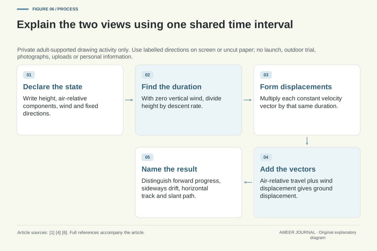
With your learning partner, choose the A example and draw a small table with three columns: air travel, air movement over ground, and resulting ground travel. Write the same eight-second duration above all three. For the rightward wind case, enter 32 metres, eight metres and 40 metres. For the leftward case, change the middle entry to minus eight and the result to 24.
Next draw the sideways case from above. Label the forward leg 32, the sideways leg 24 and the diagonal 40 metres. Ask which label answers how far forward the glider gets. The answer is 32. The diagonal answers a different, equally valid question about horizontal track length. Use written directions as well as arrows so colour is never the only clue.
Finish with one sentence explaining what stayed the same and what changed: A kept its air-relative glide while its ground path changed with the wind. Keep the drawing on screen or private uncut paper; nothing needs to be launched, photographed or uploaded. A clear explanation of those two views is the goal of this lesson.
A complete drawing record identifies H, u, s, w_x, w_y, the fixed axes and the duration rule. Compute T first, then the air and wind displacement vectors over that same interval, and finally their ground-frame sum. Equal-duration addition is essential: adding displacements from different intervals would not represent one trajectory.
For the aligned examples, show signed forward displacement. For the crosswind example, retain the ordered pair (32,24) m before computing its 40 m magnitude. Annotate the separate air-relative ratio R=4. The extra label avoids presenting a ground-track ratio of five as a new aerodynamic measurement.
The final explanation can be checked against the declared inputs without a physical activity or personal record. The original comparisons establish distinct points: the same ratio need not set duration, the same air path need not set ground reach, and the same ground record need not identify the air path. Each result follows from an explicitly stated model rather than a claim about a particular learner's plane.
Sources & further reading
Explore the references behind this guide. External pages may change after our review.
- Glide Angle | Glenn Research Center | NASANASA Glenn Research Center
- Lift to Drag Ratio | Glenn Research Center | NASANASA Glenn Research Center
- Vector Balance of Forces - Glider | Glenn Research Center | NASANASA Glenn Research Center
- Relative Velocity | Glenn Research Center | NASANASA Glenn Research Center
- Range - Constant Velocity | Glenn Research Center | NASANASA Glenn Research Center
- 4.5 Relative Motion in One and Two Dimensions - University Physics Volume 1 | OpenStaxOpenStax / Rice University
Article updated 7 Nov 2026.