What you’ll take away
- Record band, channel and width together; a channel number alone does not describe the occupied spectrum.
- A strong Wi-Fi signal can still share busy airtime or sit in front of an upstream bottleneck.
- Narrower channels offer more reuse choices; wider channels may suit capable clients in suitable lower-density conditions.
- Compare a reversible change under the same workload, location and representative conditions.
- Use the correct regional configuration and interpret channel-change events before changing protections.
Start with the problem, not the largest number
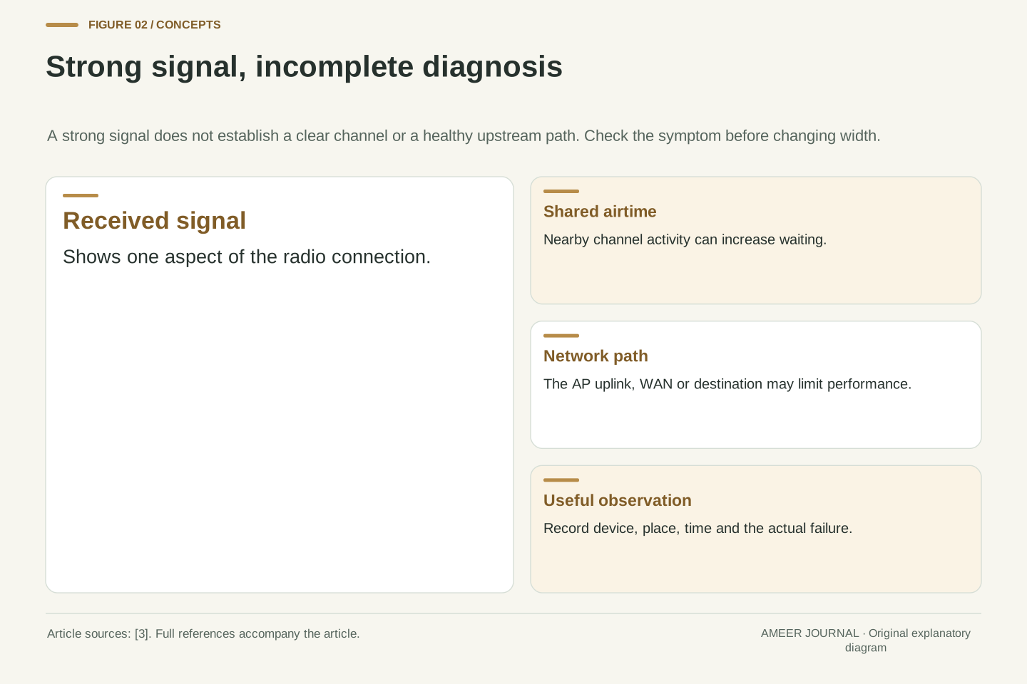
Imagine a flat where a laptop shows a strong Wi-Fi signal, yet a video meeting becomes unreliable every evening. The router offers 20, 40 and 80 MHz settings. Choosing the largest number feels like an obvious upgrade. But a strong signal does not tell you whether the channel is busy, and a wider channel does not repair a slow connection farther along the route to the meeting service. Cisco Meraki's troubleshooting guide treats those as separate questions [3]. This imagined flat is a starting point for investigation, not a test result or a diagnosis of your network.
The useful question is what the connection needs at the time it struggles. A large file transfer, a call with repeated pauses and a device that loses contact in one room are different problems to record. Write down the device, room, time and actual symptom before changing a setting. Then ask whether the difficulty follows that device, that location or the whole connection. Channel width becomes one possible explanation within that record. It earns attention when observations point toward the radio environment; it should not become the answer merely because its menu contains a bigger number.
A channel-width setting changes the spectrum available to a wireless transmission; it does not identify the bottleneck in an end-to-end application path. Meraki's current troubleshooting guidance separates radio conditions from AP uplinks, switching, addressing, DNS, WAN capacity and application behavior. It also notes that high channel utilization can increase latency even when the received signal is strong [3]. Treat width as a design variable whose effect must be evaluated against the failure being investigated, rather than as a scalar representation of network quality.
Consider a hypothetical evening video-call problem with strong RSSI and no measurements beyond the user's report. At this point, congestion on the radio channel, a time-dependent upstream bottleneck and a client-specific problem remain plausible. The appropriate first output is a scoped observation: which clients, APs, locations and times are affected, and whether a comparable wired path behaves similarly. A useful hypothesis predicts a difference that a controlled observation can expose. Increasing width before establishing that baseline changes the system without explaining it. The rest of this guide develops a way to make that decision with bounded claims and repeatable evidence.
Band, channel and width answer different questions
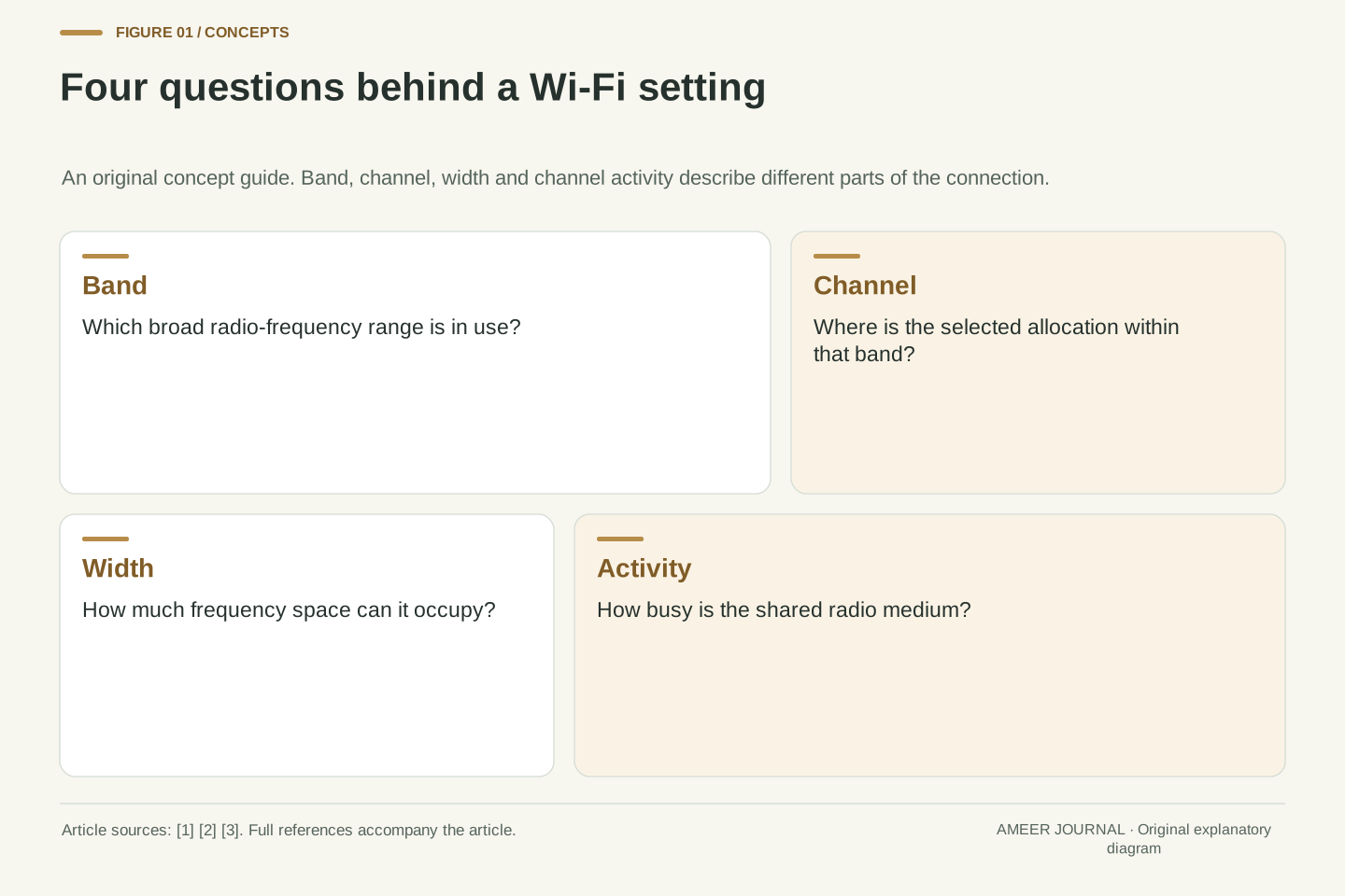
A Wi-Fi band names a broad part of the radio spectrum, such as 2.4 GHz, 5 GHz or 6 GHz. A channel selects a portion within a band. Channel width describes how much frequency space that connection can occupy, usually shown in megahertz, or MHz. Those are related choices, but they are not interchangeable. Apple lists band, channel and channel width as separate router settings [1]. A number such as 80 MHz describes a frequency span. It is not a promise that an internet download will run at 80 megabits per second.
Think of a planning sheet with three entries: which band, which channel and how wide. Changing the width while leaving the band unchanged still changes the space the radio may use. Changing the channel can move that space within the band. The devices must also support the relevant band and configuration; Meraki recommends checking client capabilities when investigating connection and performance problems [3]. For your own record, copy all three settings rather than writing only the network name. Two devices showing the same familiar Wi-Fi name do not, by that name alone, tell you which radio conditions each one is experiencing.
The band is the larger frequency allocation, the selected channel locates operation within it, and the configured width determines the nominal spectral span. Router interfaces expose these choices separately, although an automatic configuration may manage more than one of them [1]. Frequency bandwidth, measured in MHz, differs from application throughput, measured in data per unit time. A larger spectral allocation can support higher rates in suitable conditions, but the application's delivered throughput also depends on the client, radio environment and subsequent network path [3].
Record band, channel and width together when comparing observations. An SSID is the advertised network name, not a complete description of the radio allocation [1]. Likewise, a client association is not evidence that the client can exploit every capability advertised by the AP. The current Meraki guide asks administrators to relate width choices to client capabilities and site coverage [3]. In a practical comparison, keep the client and test destination fixed and record which AP or band it actually uses. Otherwise, a result attributed to width may include an unrecorded association or path change. This is a measurement-design problem before it is a tuning problem.
Different channel numbers can still share frequency space
Channel numbers are labels, not a guarantee that nearby radios have separate space. In the 2.4 GHz band, many channels overlap. Meraki's channel-planning guide and Apple's deployment guide both explain why neighboring access points (APs) need a suitable non-overlapping channel plan [2][4]. When you compare settings, look at the occupied channel ranges and their widths. A neighboring network with a different number can still overlap part of your network's range. The label alone is an incomplete description of what the radios are doing.
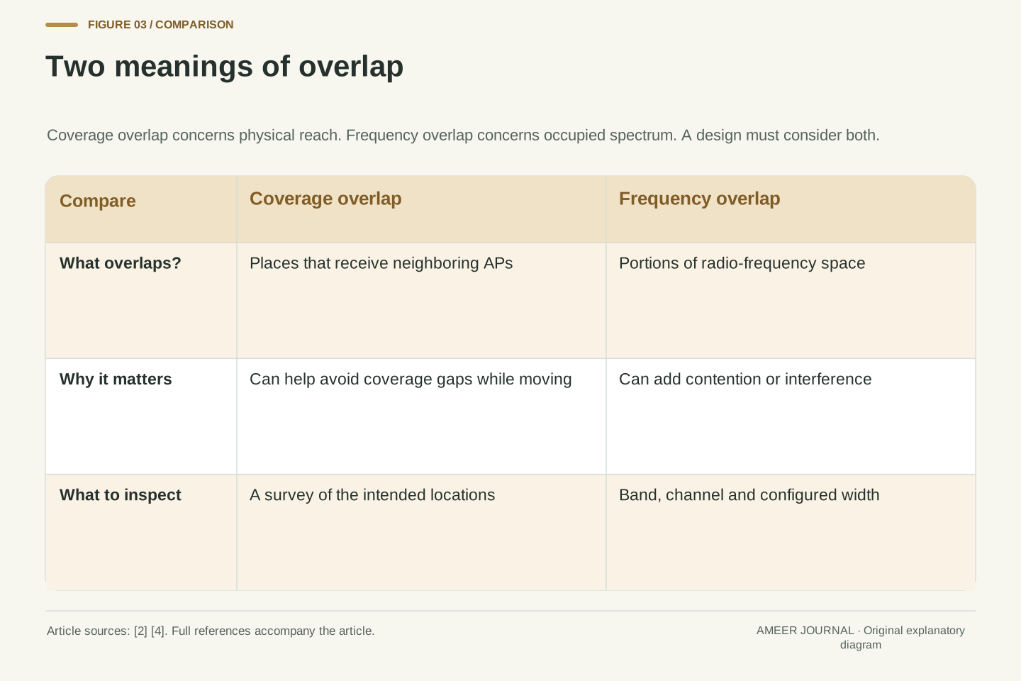
There are also two different meanings of overlap to keep apart. Coverage overlap means a device can receive neighboring access points in the same physical area. Some overlap can support movement through a building without a gap in coverage. Frequency overlap means the radio channels occupy some of the same spectrum. A deployment can need the first while trying to limit the second [2]. On a sketch of your home or office, draw where the problem occurs separately from the list of channel settings. That keeps a coverage problem from being confused with a spectrum-planning problem and makes the next question much clearer.
A channel identifier is insufficient to establish spectral separation. Meraki's planning guide describes overlapping 2.4 GHz channels, while Apple's deployment documentation also warns about overlap and explicitly scopes its channel-count examples to North America [2][4]. Compare the band and full configured width, rather than treating a changed channel number as proof of an independent allocation. This distinction also matters when wider bonded allocations consume frequency space that could otherwise support several narrower channel assignments [3][4].
Separate spectral overlap from coverage-cell overlap in the design model. Neighboring AP coverage can overlap to maintain service while clients move, yet the channel plan should reduce unnecessary same-channel contention or overlapping-channel interference in that shared area [2]. Neither a floor-plan drawing nor a channel table replaces the other. The floor plan describes where radios may interact; the channel table describes the frequency relationship. A survey connects those descriptions with observations from the intended clients [4]. This separation prevents a common reasoning error: improving the apparent coverage map while assuming that every added AP also creates new independent radio capacity.
Shared airtime and interference are related, but different
Devices using the same channel and able to sense one another generally have to coordinate access to it. Meraki describes a listen-before-transmitting check called Clear Channel Assessment. When the medium is busy, another transmission may have to wait. More active traffic can therefore create longer waits even though the connection still looks strong [2][3]. Picture several people trying to make short announcements in one room: the important observation is how much speaking is taking place, not just how many people have entered. That analogy explains waiting; it is not a complete model of every Wi-Fi feature.
Partly overlapping channels can create another difficulty. A device may not recognize an overlapping transmission in the same way it recognizes traffic on its own channel, and interference can damage frames or lead to retries [2]. For troubleshooting, ask both whether the channel is heavily used and whether transmissions are failing. A long list of visible network names alone answers neither question. Record utilization or retry information if your equipment provides it, alongside the actual application symptom. The aim is to explain the user's experience with evidence, rather than to declare a channel bad from a crowded-looking scan.
Co-channel activity and overlapping-channel interference should not be collapsed into one undifferentiated noise score. In the basic contention mechanism described by Meraki, a transmitter performs Clear Channel Assessment and defers access when it detects an occupied medium. Increasing demand can consume airtime and increase waiting even without a weak signal [2]. This is an explanation of contention, not a complete account of modern scheduling, every collision scenario or interactions among stations that cannot sense each other.
Meraki also describes how a transmission on a different but overlapping channel may not be detected by the same-channel assessment in the expected way. Interference can then produce frame loss and retransmission, adding work without delivering corresponding new application data [2]. The current troubleshooting guide recommends examining utilization, adjacent-channel activity, client distribution and interference together [3]. For a useful diagnosis, keep a distinction between offered traffic, time spent accessing the medium and successful application delivery. Counting neighboring SSIDs is useful context, but it cannot substitute for that evidence. The question is what those radios are doing during the observed failure, not simply whether their names appear in a scan.
Why sensible width recommendations differ
Apple's router guidance recommends 20 MHz for 2.4 GHz and Auto or all available widths for 5 GHz and 6 GHz when setting up networks used with Apple products [1]. Meraki's current troubleshooting guide describes 20 MHz as a common recommendation in high-density areas, while allowing that wider channels may suit a lower-density design [3]. These recommendations address different operating conditions. A quiet room with one busy connection is not the same planning problem as a building where many nearby access points need to serve active users.
Read a recommendation together with its setting and purpose. Are you trying to improve one device's transfer under favorable conditions, or provide dependable service across many neighboring connections? Which devices actually need that service? In a shared office, changing a width affects the surrounding plan as well as the person asking for more speed. Start with the equipment maker's guidance and the actual network design, then check the result. A narrow setting is not automatically the winner, and a wide setting is not an automatic mistake. The decision needs a workload, a location and observations against which it can be judged.
Apple's general router recommendations specify 20 MHz on 2.4 GHz and automatic or all-width operation on 5 GHz and 6 GHz for compatibility and performance with its devices [1]. Meraki's performance guidance treats 20 MHz as a common high-density design choice because narrower channels permit more reuse; it also says wider channels may fit lower-density deployments [3]. Apple's deployment guide independently describes the trade between narrower widths and additional channel reuse [4]. These statements should retain their deployment context rather than being merged into a universal prescription.
The decision therefore needs an explicit objective. Peak performance for one capable client, coverage across a floor and capacity for a busy group are different evaluation targets. Width selection belongs with channel assignment, client capabilities, coverage and observed utilization [3]. For an existing network, formulate a specific testable change instead of copying an enterprise setting into a home configuration or the reverse. Record the desired outcome before making the change, such as fewer call interruptions under representative load. A result that improves one favorable benchmark but worsens the intended workload is not a successful change under that objective.
A four-block example makes the trade visible
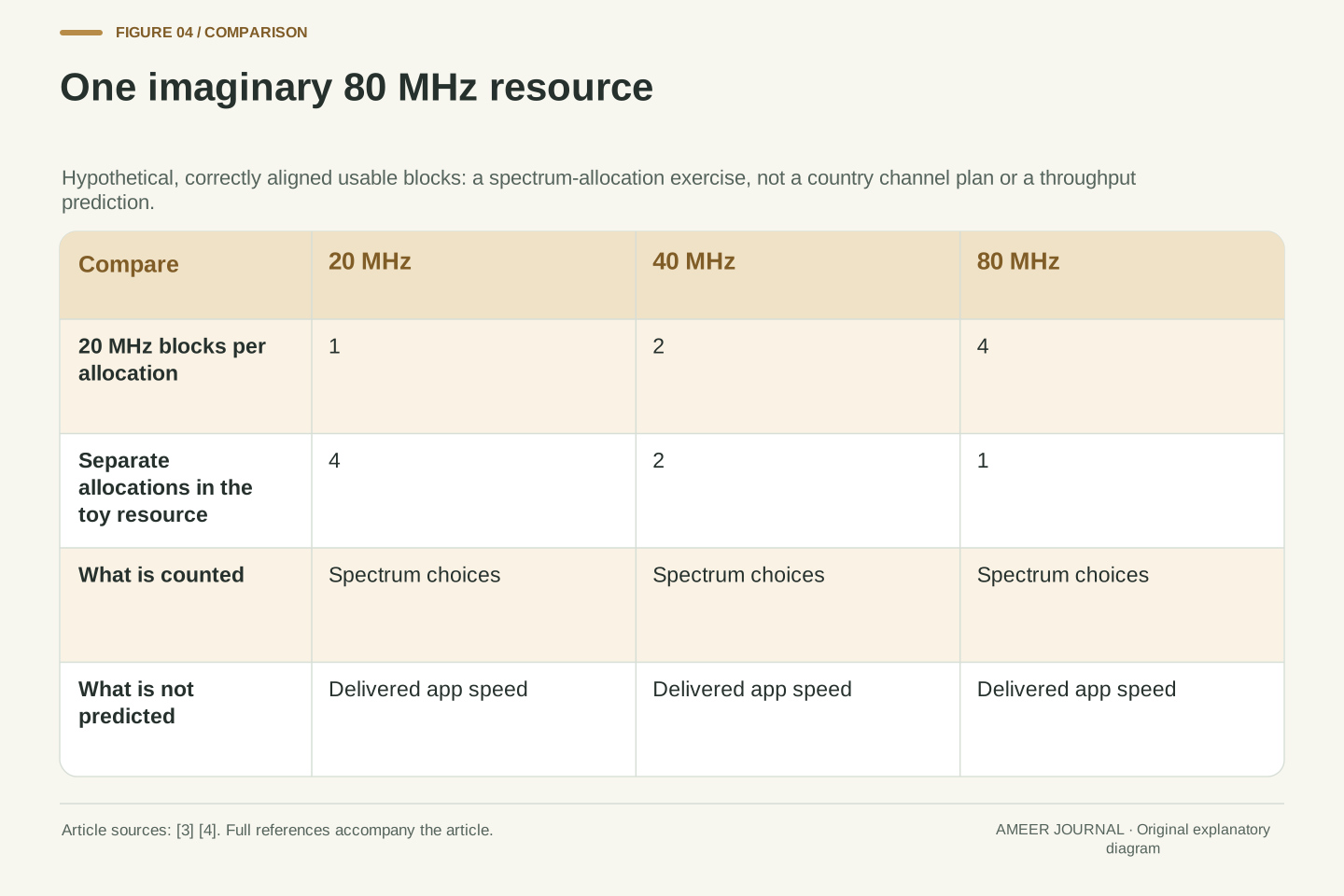
Here is an intentionally simplified example. Imagine four adjacent, usable 20 MHz blocks, correctly aligned for the wider options being compared. Together they span 80 MHz. Assume there are no extra channel restrictions in this imaginary example. You could describe that space as four separate 20 MHz allocations, two 40 MHz allocations or one 80 MHz allocation. The arithmetic is 80 divided by 20, 40 or 80. It illustrates the channel-reuse trade described in the deployment sources [3][4]; it is not a list of channels available in your country.
Now imagine four nearby APs all needing to serve users at once. Four narrower allocations give the planner more separate frequency choices within the toy space. A single wider allocation gives one connection more frequency space but leaves fewer separate choices for the others. The drawing cannot tell you which design would deliver more useful data. It leaves out signal conditions, client support, traffic demand and the rest of the network. It also does not say that each client receives an equal share. Use the example to understand what is being traded, then use real observations to choose for a real deployment.
Take a hypothetical contiguous, correctly aligned 80 MHz resource containing four usable 20 MHz blocks. For this toy allocation exercise, exclude regulatory exclusions, additional bonding constraints and other unusable portions. The number of non-overlapping equal-width allocations is 80/20 = 4, 80/40 = 2 or 80/80 = 1. This is an original arithmetic illustration of the width-versus-reuse relationship described by Meraki and Apple [3][4]. It does not model a complete physical-layer implementation or describe a real country's permitted channel inventory.
Suppose four nearby APs need resources from this constrained pool. The narrower layout permits more independent frequency assignments, whereas the wider layout allocates more spectrum to a single channel and requires more sharing or another design change for the remaining APs. No throughput result follows directly from that allocation count. Client capability, signal conditions, medium-access overhead, actual traffic and upstream limits still matter [3]. In particular, four 20 MHz allocations are not a claim of four times the delivered throughput of one 80 MHz allocation. The example deliberately stops at resource geometry so that a clear arithmetic result is not misrepresented as a measured performance result.
Make a small comparison you can interpret
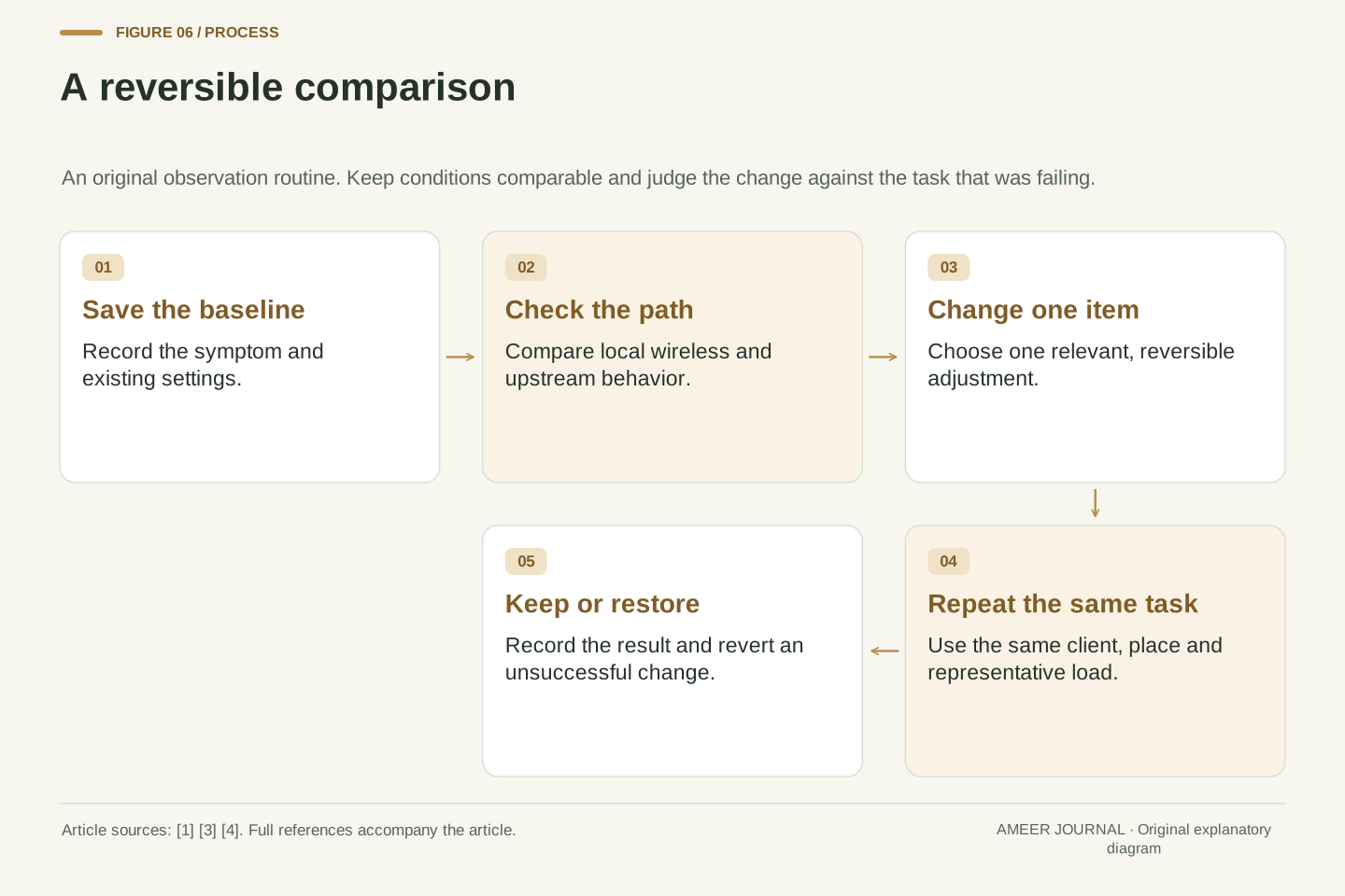
Work only on a network you administer, and save the existing configuration before making changes; Apple explicitly recommends a backup and current firmware [1]. Choose a repeatable task on the device that has the problem. Keep its location and the test destination the same. Write down the time, band, channel and width, then describe what happened: a transfer rate, delays, lost connection or a call that stayed usable. A quick result from a different room or a different device is difficult to compare with the original complaint.
If practical, compare a wired device using the same destination at roughly the same time. Meraki recommends this to help separate wireless trouble from problems farther along the network path [3]. Then change one relevant setting, repeat the same task and check again during the period that normally causes trouble. This is a suggested observation routine, not a laboratory benchmark. It cannot prove that every future evening will behave identically. It can show whether your change has a repeatable benefit worth keeping, whether it causes a new problem, or whether the evidence points away from channel width altogether.
Establish a reversible baseline. Apple recommends backing up the router configuration and maintaining current software before changing settings [1]. For a controlled comparison, preserve the client, location, destination, application task and relevant configuration as far as possible. Record the observed AP or band, channel and width alongside the result. If the device changes association between observations, record that as an additional variable rather than attributing the entire difference to the width setting.
Use the path comparison appropriate to the question. Meraki distinguishes a local wireless-to-LAN test from an internet speed test, which also includes the LAN, WAN and destination. It recommends a comparable wired check to identify common upstream degradation [3]. Repeat observations at representative busy and quiet times, and change one relevant variable before the next comparison. This proposed routine produces evidence about a specific network and workload; it is not a substitute for an engineered site survey. Keep the measurements and their conditions together. A single maximum throughput figure without those conditions has little power to explain a recurring latency or reliability complaint.
Another access point needs a channel plan too
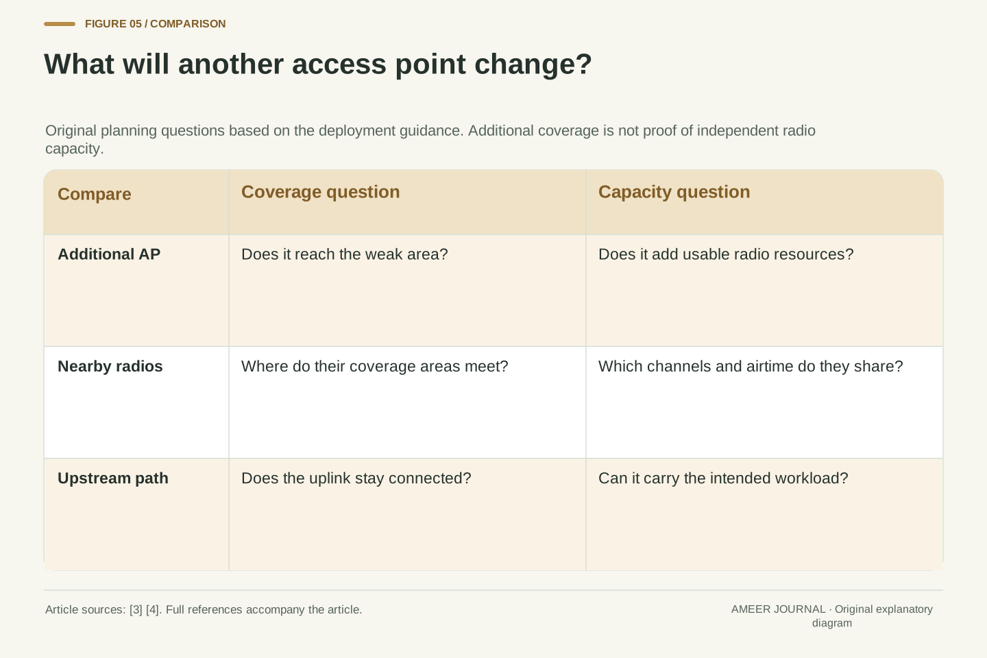
Adding an access point can help a room that lacks usable coverage, but the extra box also needs a place in the radio plan. Meraki warns that a nearby AP on the same channel with overlapping coverage does not simply add fresh capacity [3]. If the new radio shares the same busy frequency space, users may gain a stronger connection without gaining the amount of separate airtime they expected. Ask what the additional AP is intended to fix: a coverage gap, a large group of users or both.
The connection beyond the AP matters as well. A healthy wireless link cannot compensate for a troubled Ethernet uplink or an overloaded path to the service being used [3]. For a hypothetical two-room office, draw the two APs, note their channels and identify how each reaches the rest of the network. Check the weak room and the busy room separately. This simple drawing helps expose an assumption that an extra radio automatically solves both problems. It also gives an installer a clearer description than a general request to make the Wi-Fi stronger everywhere.
Coverage expansion and capacity expansion require separate evidence. Meraki's current guidance warns that adding a same-channel AP with overlapping coverage does not add independent channel capacity [3]. Apple's deployment guidance likewise relates AP quantity, placement, channel availability and expected device usage [4]. An added AP can change received signal conditions and association behavior without creating a new independent spectrum resource for the surrounding contention area. The design question is therefore which constraint the additional AP is intended to relieve.
Model the forwarding path as well as the RF arrangement. Meraki's troubleshooting sequence checks AP Ethernet link state, negotiated speed, port errors and upstream capacity before assuming that the radio is the limiting factor [3]. In an illustrative two-room deployment, record each AP's radio allocation and uplink, then compare the affected clients under the intended workload. Do not generalize a coverage improvement into a capacity claim without observing that workload. For larger installations, a preinstallation survey followed by validation under realistic conditions provides a firmer basis than choosing AP count from floor area alone [4].
Keep regional rules and client limits in the picture
A channel table from another country is not a ready-made configuration for your router. Apple notes that permitted Wi-Fi channels and signal strength depend on country or region, and its deployment guide clearly identifies the regional scope of its examples [1][4]. Use the correct regional configuration and the choices supported by your equipment. A screenshot showing extra channels on somebody else's router does not establish that those channels are suitable or permitted where you are. This article deliberately avoids a worldwide list because that would hide the conditions that matter.
Also check which devices must keep working after a change. Meraki recommends considering client band support, security compatibility and radio capability when investigating a connection [3]. Some 5 GHz channels involve Dynamic Frequency Selection, where radar detection can require a channel change; availability and client support need checking in the actual deployment [3]. If interruptions line up with recorded channel-change events, that evidence is more useful than guessing from the channel number. Preserve the equipment's required protections and ask the network administrator to interpret the logs when the network is shared or professionally managed.
Channel availability is constrained by the regulatory domain and equipment implementation. Apple's general router guidance explicitly links regional rules to permitted channels and signal strength, while its deployment guide scopes its numerical channel examples to North America [1][4]. Retain that scope when consulting a plan. Neither the abstract 80 MHz example in this article nor a vendor screenshot establishes an authorized channel set for a different installation. Use the correct regional configuration and current documentation for the actual AP and clients.
Client capabilities and regulatory behavior can also explain observations that resemble generic interference. Meraki recommends checking band and security support when an SSID cannot be seen or joined. Its DFS guidance notes that radar detection can cause channel changes and that client support varies; it recommends correlating event logs with client drops rather than disabling DFS as a blanket remedy [3]. This gives the investigation a concrete branch: determine whether the observed interruption corresponds to a channel event. A wider setting or different channel chosen without that context may hide the symptom temporarily without identifying the underlying constraint.
Choose a width with a reason you can write down
Before keeping a new setting, finish a short note: what was wrong, what changed and what improved under the same conditions. If the evidence points to crowded shared airtime, a narrower width may be worth comparing with the existing setup. If a capable device has favorable radio conditions and a workload that benefits from more bandwidth, a wider option may be suitable. The vendor guidance leaves room for both situations [1][3][4]. Keep the setting because it serves your use, not because its number looks impressive in the router's menu.
A useful closing checklist is to save the baseline, distinguish local Wi-Fi from the upstream path, check neighboring channel use, make one reversible change and repeat the task that originally failed. Restore the earlier setting if the new one causes problems or has no clear benefit. For a busy workplace or a recurring issue across several APs, pass the observations to the administrator rather than repeatedly changing radios during working hours. Your record should make the next decision easier. The best result from this process is a reliable explanation and a connection that meets the actual need.
Document the objective, baseline, intervention and result as a small engineering decision. When evidence indicates contention in a dense deployment, a narrower allocation may improve reuse opportunities; when density is lower and the client and workload can exploit additional bandwidth, a wider allocation may be appropriate [3][4]. These are conditional design choices. Compare performance against the original objective, including reliability and latency where they matter, rather than selecting a configuration from the highest observed transfer rate alone.
Retain a reproducible record: client and AP, location, band, channel, width, time, workload and observed outcome. Preserve the prior configuration so an unsuccessful intervention is reversible [1]. If the observations implicate an upstream bottleneck, client compatibility or DFS events, pursue that branch instead of continuing to vary width [3]. For a managed multi-AP network, use the record to support a coordinated survey or configuration change. A defensible conclusion might be that the current width remains appropriate and that the problem lies elsewhere. That is useful progress because it narrows the cause without turning a convenient control into an unsupported explanation.
Sources & further reading
Explore the references behind this guide. External pages may change after our review.
- Recommended settings for Wi-Fi routers and access points - Apple SupportApple · Accessed 6 Nov 2026
- Channel Planning Best Practices - Cisco Meraki DocumentationCisco Meraki · Accessed 6 Nov 2026
- Troubleshoot Wireless Client Connections and Performance Issues - Cisco Meraki DocumentationCisco Meraki · Accessed 6 Nov 2026
- Optimize your Wi-Fi networks for Apple devices - Apple SupportApple · Accessed 6 Nov 2026
Article updated 6 Nov 2026.
Found something we should revisit?
Good explanations get better with thoughtful feedback.