What you’ll take away
- The intended image and the driving sequence used to reach it are different parts of an e-paper update.
- Ghosting describes residual earlier content after an update, rather than every temporary flash.
- Fast and partial update names need the scope of the actual panel, driver and vendor support.
- Smaller image payloads do not by themselves establish proportionally faster optical updates.
- Bistable image retention does not eliminate front-light or other device energy, and a retained value may be stale.
The brief transition and the finished image are different things
An e-paper clock changes one number, but the whole screen briefly flashes. A reader turns a page and catches an inverted-looking image before the new text settles. These transitions can be part of the display’s update process. Microchip describes full refresh as a sequence that resets and redraws the screen, sometimes producing a visible flash. The purpose can include reducing traces of earlier content, rather than merely delivering the smallest amount of new picture data. [3]
A flash during an update and a faint old digit left afterwards are therefore different observations. The first may be an intermediate stage of the intended driving sequence. The second is an example of what display documentation calls ghosting: visible remnants of previous content. Different panels and update modes make different choices about speed, image cleanup and which pixels are driven. One universal explanation cannot classify every unusual screen event. [3][5]
This article follows a black-and-white electrophoretic display, then separates image data, physical updating and whole-device energy. Its pixel-count and energy-budget examples are invented calculations, not measurements of an e-reader. Vendor-specific update terminology remains identified as such. That scope lets us explain why a small visible change may involve a larger operation without treating every flash as a fault—or every persistent defect as normal. [1][3][4]
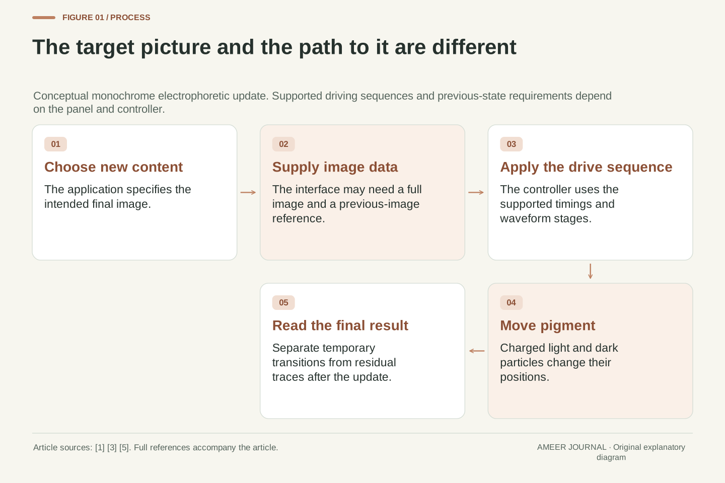
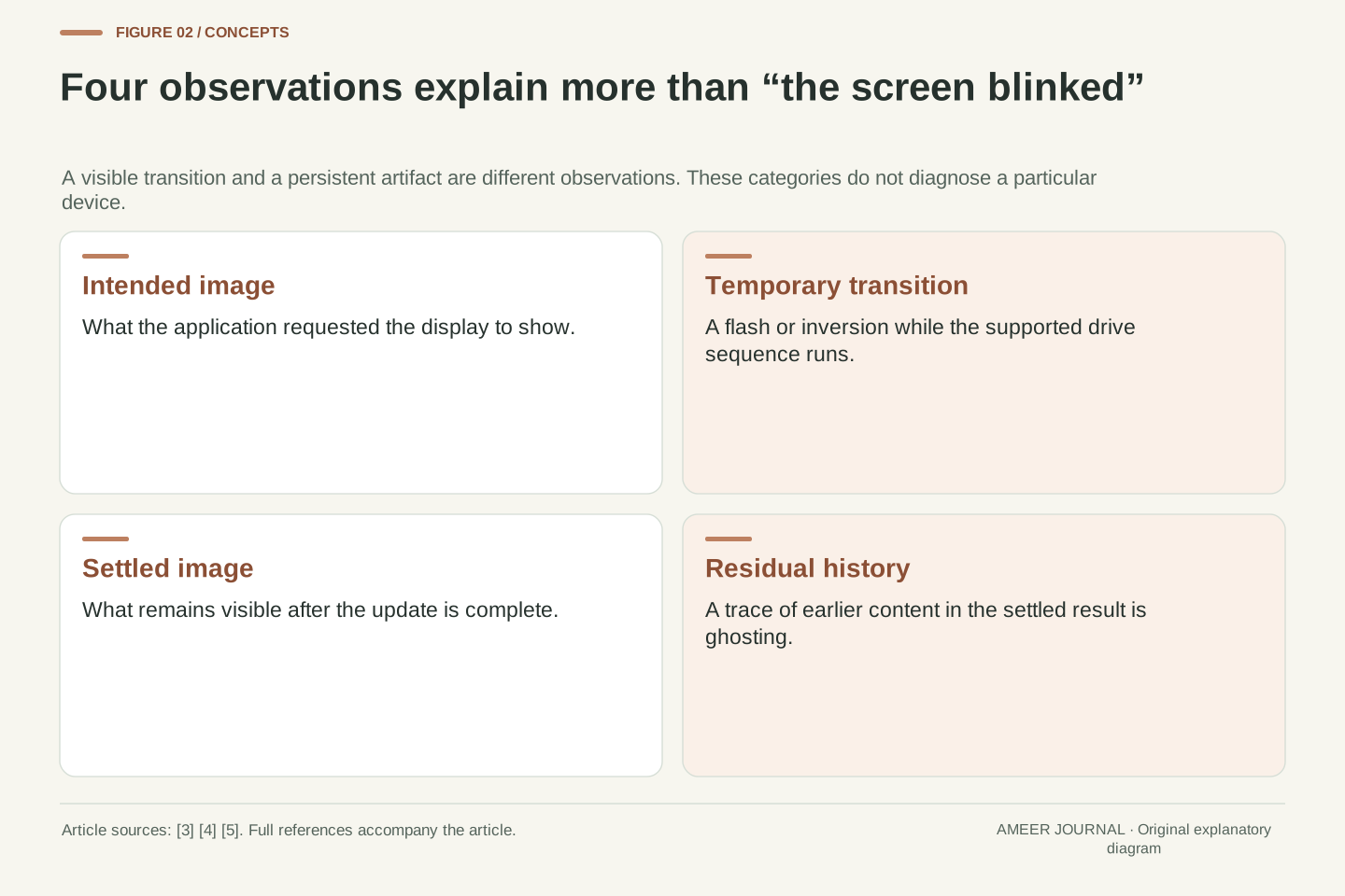
The target image and the optical trajectory used to reach it are separate objects. A small change in the target buffer need not imply a small or invisible driving sequence. Microchip’s e-paper overview describes full refresh as a complete waveform sequence that resets and redraws the display, with possible visible flashing and improved cleanup. Intermediate optical states can therefore be intentional even when only a limited part of the final image differs. [3]
Distinguish a transient update effect from residual history in the settled image. Ghosting refers to traces of previous content remaining after an update; it is not simply another name for the visible full-refresh transition. Pervasive Displays describes compensation or inverted-image driving in its update-management guidance. The relationship between those operations, elapsed time and residual artifacts depends on the panel, controller and supported update mode. [3][5]
The mechanism below concerns electrophoretic e-paper, with a two-particle monochrome example. Numerical payloads and energy terms are explicitly constructed. Product-specific mode names are not promoted into a universal protocol, and the article does not diagnose an individual panel. Instead, it separates three boundaries that are often conflated: the image representation, the physical drive operation and the energy consumed by the complete device. [1][3][4]
A pixel changes by moving pigment
In the black-and-white example, small capsules or cells contain light and dark pigment particles suspended in fluid. The two particle types have opposite electrical charges. Applying an electric field changes their positions. When light particles are presented toward the viewing surface, that location looks light; when dark particles are presented there, it looks dark. This is a physical rearrangement of pigment, not a miniature lamp switching between black and white light. [1][3]
The controller has to produce the electrical driving conditions that move the particles into the required arrangement. Pervasive Displays describes lookup tables containing timing and other driving parameters, and update stages made from multiple frames. The final black-or-white value is therefore only part of the instruction. How the panel reaches that state matters too, especially when the previous image and the new image differ. [5]
A simple way to think about the distinction is to separate a destination from the journey to it. “Show a dark pixel here” states the destination. The panel’s supported waveform supplies the drive sequence. That does not mean every e-paper technology uses the same particles, voltages or timing: E Ink describes several ink systems, while our example uses only the black-and-white mechanism needed to explain a page transition. [1][3]
A typical monochrome electrophoretic display uses oppositely charged light and dark particles suspended in a fluid. An applied field moves them toward different positions relative to the viewing surface. Presenting the light population or the dark population at that surface changes the visible state. This explanation deliberately does not assign a universal positive sign to one colour: the relevant mechanism is their charge-dependent motion under the applied field. [1][3]
The image representation specifies desired optical states, while the drive implementation supplies a time-dependent electrical sequence. Pervasive Displays documents lookup tables containing timings, data values, colour options and cycle information. It also distinguishes a frame duration from a stage comprising multiple update frames. A pixel value is consequently not a complete description of the physical operation needed to establish that pixel’s state. [5]
This distinction explains why reducing the number of changed image values need not proportionally reduce every part of the update. A controller may need transition-specific driving or cleanup according to its supported method. E Ink’s product descriptions include multiple ink organisations, so the two-particle model should remain a bounded explanation rather than a specification for colour panels or every electrophoretic product. The manufacturer’s panel and controller documentation defines the actual implementation. [1][3][5]
Holding an image is different from lighting it
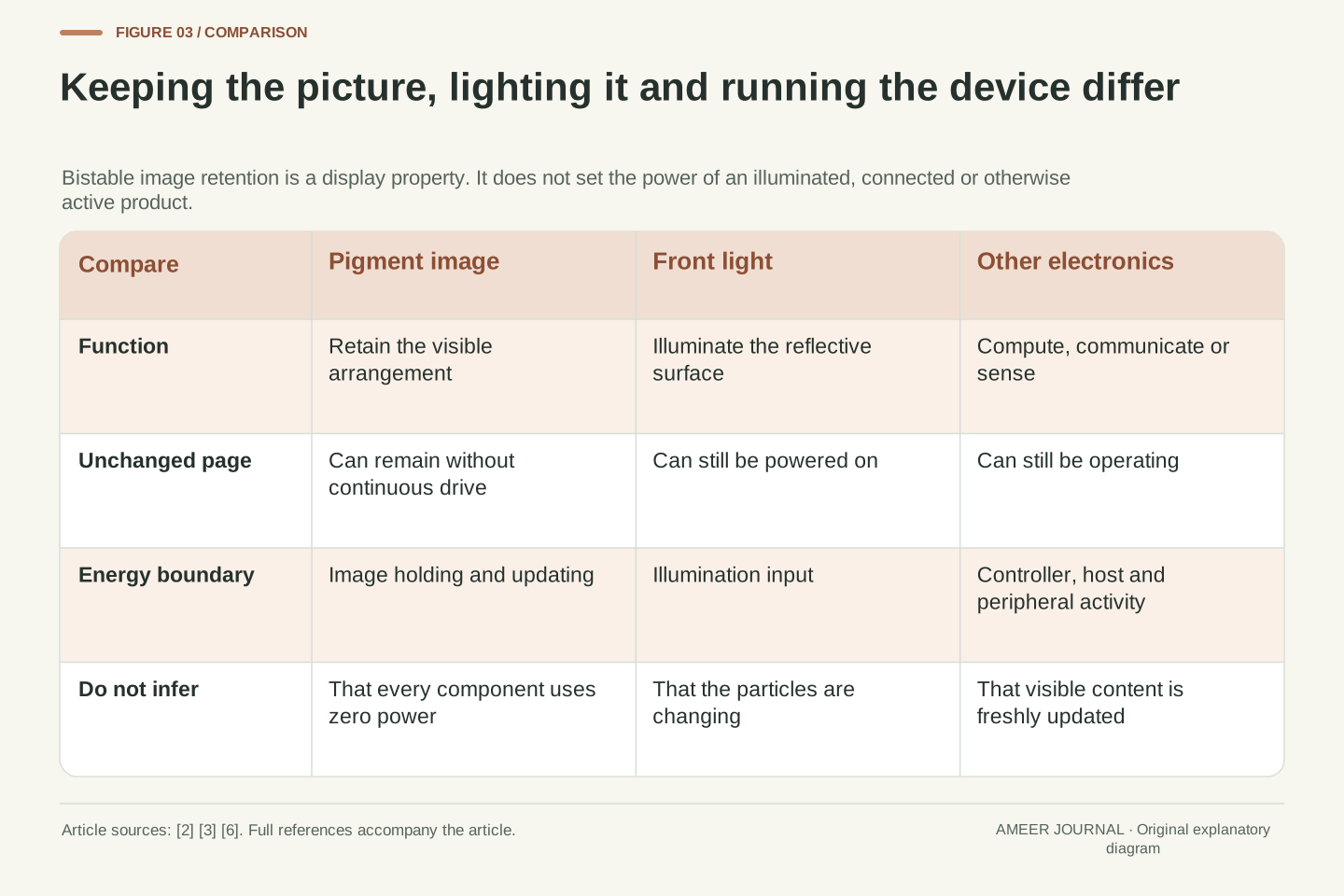
E Ink describes its image retention as bistable: the visible image can remain even after power is removed. Once the particles have reached their displayed arrangement, the panel does not need continuous refresh just to keep that image visible. This makes an unchanged page different from an image that must be repeatedly regenerated. It also explains why a powered-down e-paper device can still appear to have something on its screen. [2][3]
Seeing the image still requires light. E-paper is reflective, so ambient light can illuminate it much as it illuminates a printed page. For dim surroundings, some devices include a front light. E Ink describes a thin light guide distributing light from LEDs over the display surface, where it is reflected for viewing. Maintaining the pigment arrangement and powering that light are different tasks. Turning on illumination adds an energy input even when the words do not change. [2][6]
The rest of the device is another boundary again. Its processor, communications, sensors and other electronics may still be doing work while the screen holds an image. Microchip discusses putting controllers and other components into low-power states after updating; that would be unnecessary if retaining a picture automatically made every component consume nothing. Read a no-power image-holding claim as a claim about that display behaviour, not a complete battery-life calculation. [3]
Bistability separates optical retention from continuous driving. E Ink states that an image can persist after all power sources are removed, and Microchip describes retaining visible content during sleep or low-power operation. The useful claim is that an established optical state does not require continuous refresh solely to remain visible. It does not establish the quiescent consumption of the controller, host processor or assembled product. [2][3]
Reflection and illumination are separate mechanisms. Ambient light can supply illumination, while an integrated front light supplies it electrically in dim conditions. E Ink describes edge-mounted LEDs and a thin light guide distributing light across the viewing surface. That lighting system can consume energy while the electrophoretic state remains unchanged. The image-holding term and the illumination term must therefore remain separate in a product energy model. [2][6]
Likewise, retained content does not prove that the host is asleep. Microchip’s power-aware guidance explicitly treats display updating, controller state, MCU state and peripheral state as coordinated choices. A product can retain its last picture while a processor or radio continues operating, or retain it after those components stop. The display’s visible state alone is insufficient to infer either current power consumption or current system activity. [3]
The previous image can affect the next transition
Suppose yesterday’s dark number leaves a faint outline behind today’s number. The display has not necessarily received a file containing both numbers. Ghosting means that traces of a previous displayed state remain visible after the update. Microchip identifies it as a consideration particularly with partial refresh, and notes that periodic full refreshes may be needed depending on the display and controller. The final visible result must be checked separately from the intended picture. [3]
Pervasive Displays’ fast-update method explicitly uses both previous and new image data. The comparison identifies what changes, and the resulting new image becomes the previous image for the following update. That history is part of this documented method. Supplying a target picture alone is not always enough information to describe the transition the driver expects. An image buffer and the actual screen also need to remain consistent within the chosen implementation. [5]
The same vendor describes cleanup using compensation or an inverted image during suitable global updates. This helps explain why an occasional more visible transition can be worthwhile. It does not create a universal rule such as “every screen must flash after five changes”. The relevant schedule depends on the supported panel, drive method, conditions and acceptable image quality. Use the manufacturer’s actual guidance instead of transferring a count from an unrelated module. [5]
Residual image history is an optical state problem, whereas a target-buffer error is a content problem. Ghosting is defined by traces of previous content remaining after updating. Microchip links its likelihood and cleanup requirements to refresh mode, panel and controller. A correct target buffer is therefore not sufficient evidence that the intended final optical state has been achieved. Conversely, a cleanly displayed wrong target should not automatically be labelled ghosting. [3]
Pervasive Displays documents a history-dependent fast-update path using old and new image buffers. Equal and changed values are handled differently, and the newly displayed result becomes the reference for the next comparison. These requirements make the buffer sequence part of correct operation. The example should not be generalised to every controller interface, but it demonstrates why the previous state cannot always be discarded simply because a new image is available. [5]
Its management guidance also describes compensation or inverted-image driving and suitable global updates to control residual effects. The published recommendations depend on use case and image-quality tolerance. The inference is a trade-off between a particular transition strategy and optical cleanup, not a fixed universal refresh interval. Changes to a waveform’s timing are consequently implementation changes, not merely a cosmetic preference for less flashing. [5]
Full, fast and partial do not describe one universal scale
Two questions help untangle update names. How much image data is sent to the controller? And how does the panel drive its pixels? A smaller upload and a faster visible update are related possibilities, but they are not the same operation. Microchip describes partial refresh as updating a selected display region. Pervasive Displays gives a more specific distinction between its fast-update method and its partial-window method. [3][4]
In Pervasive Displays’ documented fast update, a full image is sent and the driver compares old and new data. Its partial update instead sends data for a defined window. The vendor’s current retrieved update page also states that partial-update support has been suspended and recommends fast update, explaining concerns about pixels outside the window. That is a statement about this vendor’s documented support, not a ban on partial refresh across the entire e-paper industry. [4][5]
For a finished reader or status display, the useful question is which modes that exact device supports and how it chooses among them. A menu called “fast” does not tell you its payload size, colour support, cleanup policy or final image quality by itself. For a developer, selecting an update method requires the panel-and-driver combination to support it. The words on an unrelated product page cannot establish that compatibility. [3][4]
Separate host-to-controller data transfer from panel driving. An update may upload a complete frame yet reduce the optical work applied to unchanged pixels; another interface may accept a smaller region. Microchip’s general full/partial distinction and Pervasive Displays’ specific normal/fast/partial table illustrate why terminology should be interpreted within its documentation rather than treated as an interchangeable industry-wide API. [3][4]
In Pervasive Displays’ description, fast update sends full-screen image data for comparison, with previous and new buffers. Its partial mode restricts the transferred image to a defined window. The retrieved page includes an explicit notice suspending Partial Update support and recommends Fast Update, citing degradation of unchanged pixels outside the partial window. Preserve that scope: the notice qualifies this vendor’s documented implementation and does not establish that all other controllers have withdrawn region updating. [4][5]
A meaningful mode specification should identify supported panel type, data representation, previous-state requirements and actual driving behaviour. “Fast” alone supplies none of those boundaries. It also does not prove that a shorter host transfer produces the same final optical quality. Evaluate the supported combination and its documented trade-offs before comparing timings or designing a refresh policy. This keeps an attractive mode name from replacing the information needed to operate the display correctly. [3][4][5]
A hundredth of the picture data is not a timing guarantee
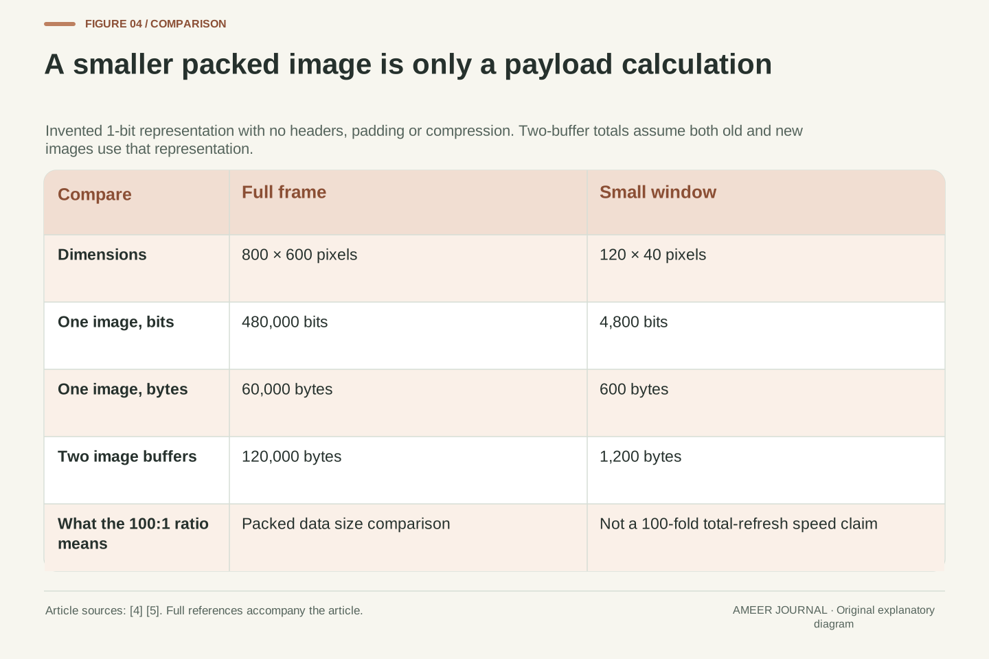
Consider an invented monochrome image 800 pixels wide and 600 pixels high stored with exactly one bit per pixel. It contains 480,000 bits, or 60,000 bytes. A window 120 pixels wide and 40 pixels high contains 4,800 bits, or 600 bytes. The window holds one hundredth as many packed image bytes. These counts ignore headers, row padding, compression and any extra controller-specific information; they describe only the stated picture representation.
If a hypothetical protocol required both an old and a new packed image, the corresponding two-image amounts would be 120,000 bytes for the full frame and 1,200 bytes for the window. The ratio is still 100 to 1. But the documented Pervasive fast-update method can upload full frames even when only a small visible area changes. The small changed area is not, by itself, evidence that only 600 bytes were transmitted. [4][5]
Nor does the byte ratio prove that the screen finishes 100 times sooner. Uploading data is one stage; applying the waveform and allowing the optical transition to complete are others. Pervasive Displays explicitly describes multiple update frames within a drive stage. A smaller payload can reduce one part of the work while another part still determines when the new image is ready to read. Measure the relevant interval before comparing complete update times. [5]
For a constructed tightly packed 1-bit image, Nfull=800×600=480,000 bits, so Sfull=Nfull/8=60,000 bytes. A 120×40 window gives 4,800 bits and 600 bytes. The payload ratio is 60,000/600=100. This is a representation calculation, not a controller datasheet: row alignment, command bytes, additional image planes, compression and transfer granularity are explicitly excluded.
If both previous and new buffers were transmitted in that same representation, their totals would be 120,000 and 1,200 bytes respectively, retaining the 100:1 ratio. Pervasive Displays’ actual documented fast path nevertheless uses full-screen previous/new information. A changed bounding rectangle and a transferred payload are therefore different quantities. The application must know whether the selected interface really accepts a region or requires complete frame data. [4][5]
Total update latency also includes the drive sequence. Pervasive Displays distinguishes update frames from stages containing multiple frames; those optical-driving durations are not specified by the file-size calculation. Even a reduction by a factor of 100 in transferred bytes establishes neither a reduction by a factor of 100 in total latency nor equivalent cleanup. Define whether timing covers host transfer, panel busy time or the settled visible result before interpreting a reported improvement. [5]
The operating conditions belong with the update mode
A display that updates differently in cold conditions is not being described fully by its pixel count. Microchip explains that lower temperatures can slow particle movement and increase refresh time, while higher temperatures can affect appearance depending on the panel. The exact allowed conditions come from the panel specifications. A refresh-time claim without its temperature and mode leaves out part of the mechanism. [3]
The driving sequence matters as well. Pervasive Displays describes lookup tables containing timings, cycles and other parameters. Those values belong to a particular panel and driver implementation. Copying a faster waveform from another module, or simply shortening its stages, changes how the material is driven. The documentation directs such changes toward vendor support rather than treating them as a universal speed switch. [5]
For an ordinary reader, keep the practical observation precise: which page or area changed, which mode was selected, what conditions the device was in, and what remained after the update finished. Those details distinguish a normal visible transition from an unwanted final artifact much better than “the screen blinked”. For a developer, include the exact panel and driver versions and the previous/new-image sequence when reporting a problem. [3][5]
Temperature is an operating variable, not an incidental detail beside a refresh specification. Microchip describes slower particle motion and increased update time at lower temperatures, with high-temperature effects dependent on the panel. This supports recording temperature alongside mode and panel identity; it does not supply one universal operating range or temperature correction factor. The actual panel specification constrains both use and interpretation. [3]
Waveform parameters are likewise implementation-specific. Pervasive Displays describes LUT content involving timings, data, colour options and cycle counts, and directs developers seeking altered stage timing toward vendor support. Reducing stage duration changes the physical drive applied to the material. A seemingly faster update can therefore trade against settling or image quality rather than represent an unconditional software optimisation. [5]
A useful observation record includes initial content, requested content, mode, environment, sequence and final optical result. In the documented old/new-buffer method, verify the correspondence between the prior displayed frame and the supplied reference rather than assuming the newest buffer contains all necessary state. These checks narrow an investigation without prescribing unsupported voltage, timing or control changes. They also keep a transient flash distinct from an artifact that remains after completion. [3][5]
Calculate the whole device rather than only the held image
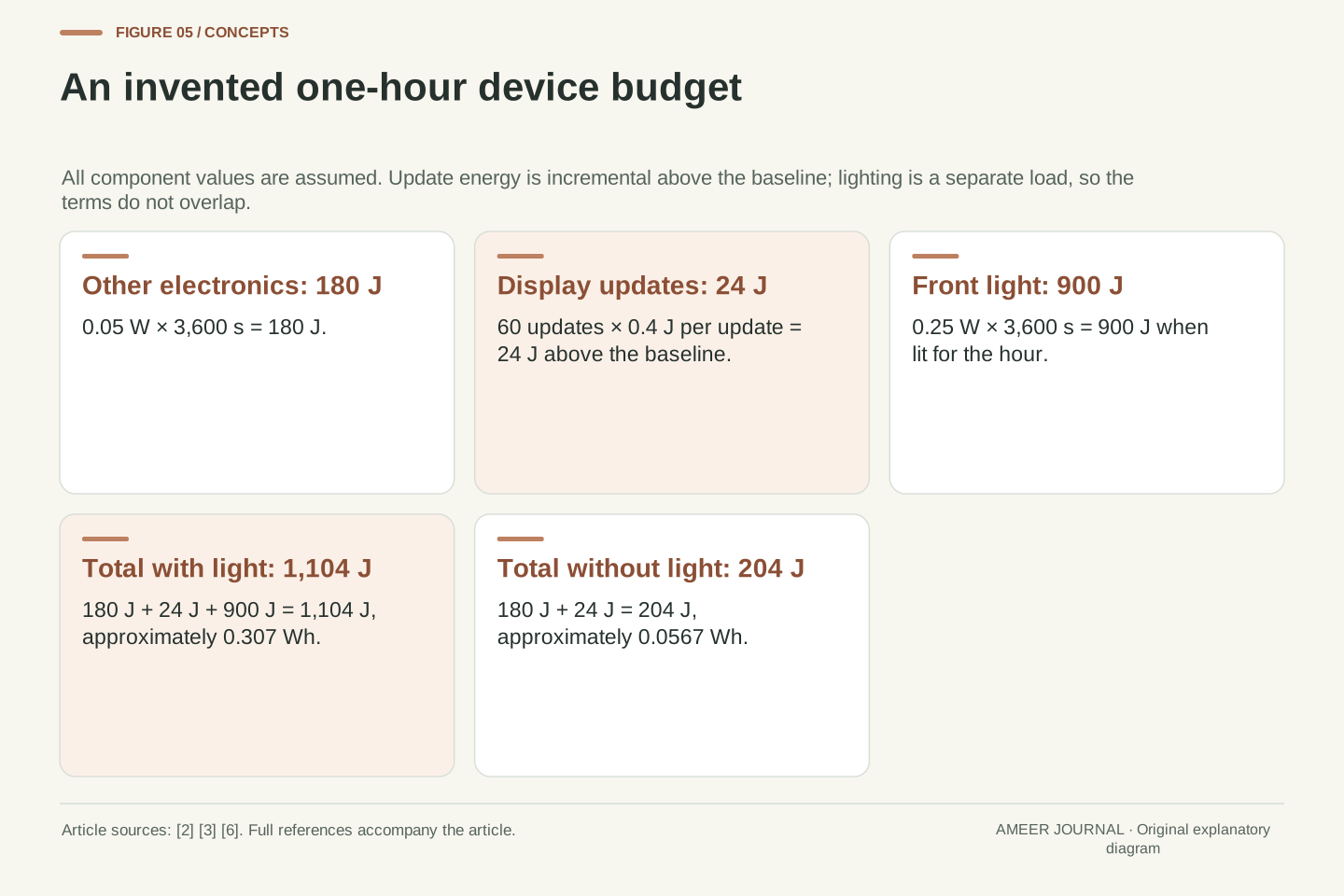
Take an invented one-hour operating period. Assume other device electronics draw a constant 0.05 W, and each of 60 display updates consumes an extra 0.4 J above that baseline. The electronics use 0.05×3,600=180 J. The updates add 60×0.4=24 J. Together, those terms use 204 J even though maintaining the settled pigment image requires no continuous drive. The update term is additional energy, so the same baseline is not counted twice. [2][3]
Now assume a front light uses another 0.25 W for the entire hour. It adds 0.25×3,600=900 J. The total becomes 180+24+900=1,104 J, about 0.307 Wh. These are invented component values chosen to make the boundaries visible. The front light illuminates the image; it does not need to change the particles to consume energy. A static page and a lit device can therefore coexist with continuing battery use. [6]
If the front light is off in this model, the total returns to 204 J, about 0.0567 Wh. Actual battery life would also need the real battery’s usable energy and the device’s changing behaviour. The calculation’s useful lesson is the separation: image holding, update energy, other electronics and illumination are distinct terms. A claim about any one of them cannot silently stand in for all the others.
Define an illustrative one-hour budget with baseline power Pbase=0.05 W excluding the separately counted update increment and front light. For t=3,600 s, Ebase=Pbase×t=180 J. Let each of n=60 updates require an incremental 0.4 J above that baseline, giving Eupdate=n×0.4 J=24 J. The total without illumination is 204 J. Bistable optical retention does not remove either of these explicitly assumed system terms. [2][3]
Add a separate front-light load of Plight=0.25 W over the same interval. Elight=900 J, and Etotal=180+24+900=1,104 J. Using 3,600 J per Wh gives 0.306667 Wh. The model is additive because its terms are defined not to overlap. If the 0.4 J figure instead included baseline or lighting energy, adding those components again would be incorrect. E Ink’s light-guide description establishes why illumination is a distinct function; the numerical values remain invented. [6]
Removing the lighting term leaves 204/3,600≈0.056667 Wh for this interval. Neither number is a device rating or a prediction of battery endurance. Such a prediction would require usable battery energy and a representative duty cycle, including the actual relationship between updates, sleep and other activity. The budget instead demonstrates why a zero continuous image-holding term does not imply zero complete-device energy consumption. [2][3]
An image that remains visible may no longer be current
Persistent content has another consequence: the screen can keep showing a value after the device stops obtaining fresh information. A retained sensor reading does not prove the sensor has just measured it. A retained page does not prove a wireless connection is active. This follows directly from the ability to hold an image after power is removed. The visible content and the process that produced it can have different lifetimes. [2][3]
For an invented room-status display, a clear last-updated time can help the reader interpret a value that stays visible. The timestamp itself will also remain if updates stop, so it should be understood as evidence of the last update, not as a live heartbeat. Likewise, an interface can group changing information into a defined area while leaving explanatory labels stable. Microchip recommends separating dynamic content and avoiding unnecessary full-screen changes, subject to the available update modes. [3]
That creates a useful design balance. Keep information readable, make the age of time-sensitive content understandable, and avoid suggesting that every tap will produce an immediate fluid animation. Microchip recommends feedback when updates take noticeable time. A clearly communicated update cycle can be easier to use than an interface that hides its delay and leaves the reader unsure whether the requested change was accepted. [3]
Bistability decouples image persistence from system liveness. Because the panel can retain content after power removal, a visible measurement does not establish continuing acquisition, communication or successful recent computation. This is an inference from the documented retention mechanism, not a claim about the failure mode of a particular status product. The display state and the provenance time of its information should be treated as separate attributes. [2][3]
A fictional status panel can expose an observation or last-update timestamp alongside a value. That timestamp is also persistent, so its meaning is historical unless a new update occurs. Grouping dynamic fields into a defined region may simplify a supported update strategy, but does not itself prove that the driver transmits or drives only that region. Microchip’s interface guidance recommends logical grouping and reduced unnecessary changes; the actual mode capabilities still constrain the implementation. [3][4]
User feedback should also distinguish request acceptance from completed visual change where the interaction needs that distinction. Microchip notes that visible update delays affect GUI design. A deliberate presentation of update state can therefore improve interpretation without pretending the panel behaves like a continuously animated interface. Evaluate the task and update cycle together: stable content is valuable, but stale content and unacknowledged input can create different usability problems. [3]
Read the update as a documented sequence
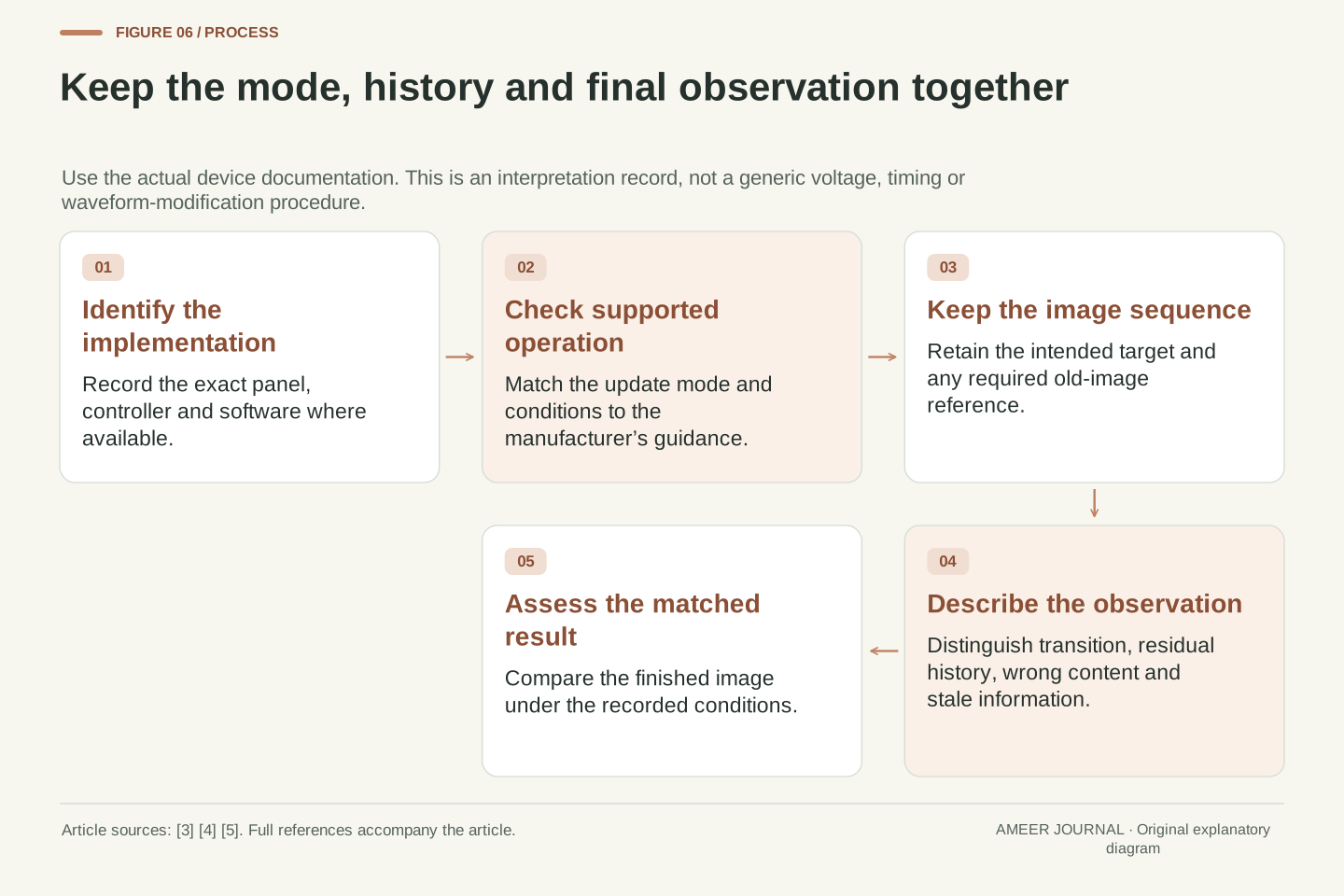
Begin with the exact device or panel and its supported software. Then identify the update mode and the conditions under which it is being used. Ask whether the observation concerns a temporary transition, a residual trace in the finished image, an incorrect target image, or a value that has simply stopped changing. These descriptions point to different evidence and avoid treating every unusual appearance as the same kind of problem. [3][4][5]
For a developer, keep the previous and new images, the relevant driver settings and the sequence of operations when the interface requires that history. For a finished product, use its own refresh options and guidance. Manufacturer-specific waveform or support restrictions should travel with the instructions; a mode advertised for another panel does not establish a safe or correct replacement. The documented Pervasive distinction between fast and partial updating is a concrete reason to check. [4][5]
The flash now has a clearer place in the story. It can be part of moving pigment through a supported cleanup sequence, while ghosting describes what may remain afterwards. Smaller picture data can reduce an upload without determining every physical update stage. A held image can require no continuous drive while illumination and electronics still use energy. Keeping those boundaries visible makes e-paper’s distinctive behaviour easier to interpret. [2][3][5][6]
A reproducible update description retains panel identity, controller and software version, supported mode, operating conditions, target content and final observation. Where the method uses old/new buffers, preserve their sequence as well. Identify whether the issue lies in requested data, transition behaviour, settled optical quality or information freshness. These categories are related but require different evidence. [3][4][5]
Use manufacturer-supported driving procedures and support status for the exact implementation. Pervasive Displays’ fast-update buffer requirements, LUT discussion and suspended partial-window support are scoped examples of constraints that a generic mode label cannot express. They do not supply universal register values or cleanup counts. A review should establish whether the chosen operation is documented before comparing its visible result with a different panel or driver. [4][5]
The mechanism then remains consistent across the article: image data describes desired content, electrical driving establishes an optical state, bistability retains that state, and illumination makes it visible in the available light. Payload size, refresh latency, residual image quality and complete-device energy measure different parts of this process. Compare each at its stated boundary, and use a matched observation rather than a single flashing event to assess what happened. [1][2][3][5][6]
Sources & further reading
Explore the references behind this guide. External pages may change after our review.
- Electronic Ink|E Ink TechnologyE Ink · Accessed 6 Nov 2026
- Benefits|E Ink TechnologyE Ink · Accessed 6 Nov 2026
- ePaper Display Fundamentals - Developer HelpMicrochip Technology · Accessed 6 Nov 2026
- Updating the display - Pervasive Displays Knowledge BasePervasive Displays · Accessed 6 Nov 2026
- Management - Pervasive Displays Knowledge BasePervasive Displays · Accessed 6 Nov 2026
- Front Light|E Ink TechnologyE Ink · Accessed 6 Nov 2026
Article updated 6 Nov 2026.
Found something we should revisit?
Good explanations get better with thoughtful feedback.