What you’ll take away
- A bypass diode adds a parallel route; it does not automatically disconnect the protected source branch.
- The shared series current applies to each complete group, while its internal source and bypass currents can differ.
- In the original ideal example, a 3 A string current divides into 2 A through the weak source and 1 A through the bypass.
- A nonzero bypass drop makes diode dissipation different from the total protected-group absorption.
- Connected-string power, separate component maxima and an all-bright reference require different comparisons.
- The source curves and allowed output range determine which power peak is available; group count alone is insufficient.
A bypass path changes the current route, not the identity of the cells
When part of a solar string is shaded, a bypass diode can provide another route for current. It is tempting to picture the shaded cells being switched off and every ampere taking the new route. That picture misses an important connection: the diode sits across a cell or protected group, while the original source branch remains connected between the same two terminals [1].
The current entering that protected assembly can therefore divide between two internal branches. Knowing the current through the string does not, by itself, tell us the current through the bypass diode. The voltage across the assembly and the source's own current–voltage relationship are needed as well. This distinction also changes how we account for power.
We will follow three invented source groups using simple straight-line relationships. Two represent brighter groups and one a weaker group. These are teaching definitions, not measurements of a panel or a physical fit to shading. First the bypass has zero voltage drop; later it has a separately assigned drop. Keeping those assumptions visible lets us calculate exactly what each route carries.
A bypass diode is connected across a photovoltaic cell or group with polarity opposite to normal generating voltage [1]. The protected assembly is thus a two-terminal parallel combination, not a series disconnect. Its external current and the current in either internal branch are different circuit variables. Confusing those boundaries can turn a correct string-current statement into an incorrect diode-current statement.
This article constructs an affine source model to expose that distinction. Its original calculations cover internal current division, signed power, the assembled string characteristic and several reference maxima. No physical module, photovoltaic simulator or tracking algorithm supplies the assigned values. The model is deliberately simpler than a semiconductor characteristic, and it resolves only group terminals rather than individual cells inside a group.
We use a generating sign convention: positive current flows through a source from its designated negative terminal toward its positive terminal. Positive terminal voltage multiplied by that current is delivered electrical power. A bypass branch uses the same current reference direction. The names of the terminals remain fixed even if the operating voltage becomes negative.

Define the groups before combining their voltages
Place three source groups in one series string. Call them Bright One, Bright Two and Weak. The same external current passes through each complete group. Their voltages add to give the string voltage, as described in Sandia's array-modeling guide and PVsyst's curve-combination explanation [2][3]. Sharing current does not require the three voltages to be equal.
Each bright group follows this invented rule: start at twelve volts, then subtract two volts for every ampere through it. At one ampere, each provides ten volts. At three amperes, each provides six. The weak source starts at ten volts and loses five volts for each ampere through its own source branch. At one ampere it provides five volts; at two it reaches zero.
Only Weak has a bypass path in this construction. We must distinguish the current through the entire protected group from the current through its source branch. The two are equal while the bypass carries nothing. Once the bypass conducts, the string current can exceed the source-branch current without violating the series connection.
Write i=I/(1 A) for normalized string current and j=J/(1 A) for normalized weak-source current. Each bright group has V_b=(12−2i) V. The weak source has V_w=(10−5j) V. The coefficients are explicit teaching parameters, not irradiance-dependent values inferred from a real module. The main ideal construction uses 0≤i≤6, keeping each bright-group voltage nonnegative.
The two bright groups carry I individually. The third series element is the complete parallel combination of the weak source and its bypass. If the bypass current is D, conservation at that assembly gives I=J+D. Thus the series rule applies to the external port current I; it does not impose J=I when D is nonzero.
After solving the weak assembly, combine the groups through V_string=2V_b+V_w. This follows the common-current series composition described by the primary references [2][3]. Adding component voltages evaluated at unrelated currents would not produce a valid string characteristic, even if each separate pair were internally consistent.
The bypass condition depends on the voltage across its own terminals
During ordinary positive-voltage generation, the oppositely connected bypass diode blocks its branch. If the protected group is driven toward a sufficiently negative voltage, the diode can conduct in its forward direction [1]. Saying that shade has appeared is therefore not a complete description of the diode's state. The operating current and the resulting group voltage also matter.
Begin with an ideal bypass that carries current with exactly zero voltage drop. In this model it blocks whenever the weak group's voltage is positive. If the source alone would require a negative voltage, the bypass instead holds the group at zero while carrying the additional current. Real diode behavior is not an exact zero-voltage switch; this is a declared simplification.
At one ampere the weak source supplies five volts, so the ideal bypass remains inactive. At two amperes the source reaches zero volts and the bypass current is still zero. Beyond that point, the zero-voltage condition determines the source current, and the bypass carries the difference needed by the string.
Let d=D/(1 A) and v_w=V_w/(1 V). The ideal bypass is defined by v_w≥0, d≥0 and v_w d=0, together with i=j+d and v_w=10−5j. These complementary conditions express a blocking branch at positive group voltage and a conducting zero-drop branch. They are model equations, not a claim about an intrinsic physical turn-on threshold.
If d=0, then j=i and v_w=10−5i. This branch is valid only for i≤2. If d>0, then v_w=0, so j=2 and d=i−2; this branch requires i>2. At i=2 both descriptions meet with v_w=0 and d=0. There is one operating point at the boundary, not two different currents.
The opposite-polarity topology is supported by the bypass explanation [1]. Its actual semiconductor behavior is intentionally replaced here by the ideal conditions. We therefore derive the branch transition from those conditions rather than treating a particular fraction of shade, a cell count or a fixed real diode voltage as the switching rule.
Three amperes through the group need not mean three through the bypass
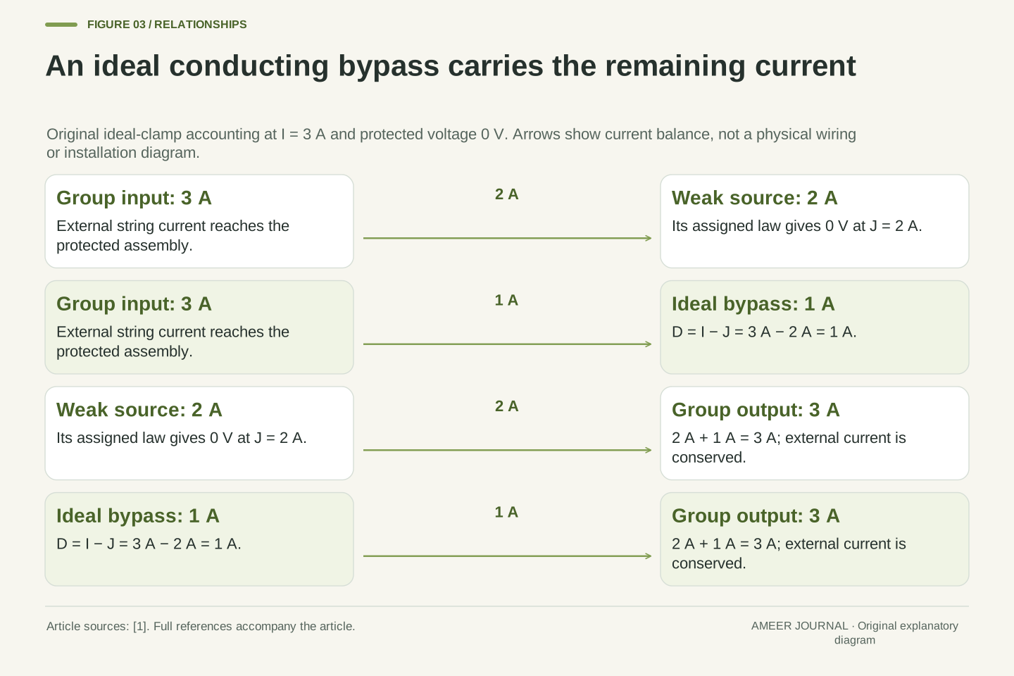
Set the string current to three amperes. The ideal bypass holds Weak at zero volts. Its source rule then says that the source branch carries two amperes: ten volts minus five volts per ampere times two amperes is zero. The remaining one ampere flows through the bypass. The two internal currents add to the three amperes passing through the whole group.
At four amperes, the same ideal clamp still leaves two amperes in the source branch, while the bypass carries two. At one ampere, all one ampere goes through the source and none through the bypass. These are three operating points of one unchanged construction, showing why the label bypass on does not specify a unique diode current.
The result does not mean that the source is delivering useful electrical power while clamped at zero volts. Its net terminal power is zero because its voltage is zero. Current flow and delivered power are separate quantities. A nonzero current through a branch is compatible with zero net electrical power at its two terminals.
At I=3 A, the conducting ideal branch fixes V_w=0 and J=2 A. Kirchhoff's current balance gives D=I−J=1 A. Both bright groups carry 3 A, but the weak source and bypass carry 2 A and 1 A respectively. There is no contradiction with a series string: the branch split occurs inside one of its two-terminal elements.
At I=4 A, the weak-source current remains 2 A and the bypass current becomes 2 A. At I=1 A, V_w=5 V, J=1 A and D=0. The equality I=J+D holds at every point. These values are consequences of the assigned affine source and ideal diode, not universal current fractions for a shaded panel.
For the ideal conducting branch, V_w J=0 and V_w D=0. Their sum is V_w I=0, the net terminal power of the protected group. This statement concerns the lumped model's ports. It does not resolve internal photon absorption, recombination, heat flow or the power of individual cells hidden inside an actual protected group.
A negative group voltage changes the power balance
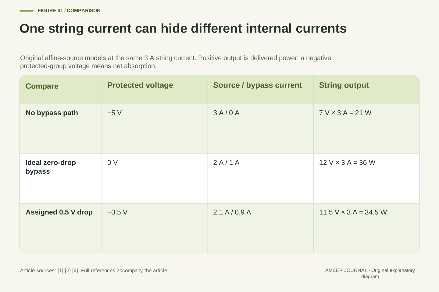
Compare two mathematical circuits at the same three-ampere string current. Remove the bypass in the first circuit while keeping the source relationships unchanged. Weak must now carry all three amperes, so its voltage is ten minus fifteen, or negative five volts. Each bright group still provides six volts. The complete string therefore provides seven volts and twenty-one watts.
The negative weak-group voltage matters. Under our sign convention, three amperes times negative five volts is negative fifteen watts: the weak group absorbs that much net electrical power. The two bright groups together deliver thirty-six watts, leaving twenty-one watts at the string output. Power has not vanished from the accounting.
Restore the ideal bypass at the same three amperes. Weak is now at zero volts, the string provides twelve volts and its output is thirty-six watts. The improvement comes from avoiding the modeled negative group voltage. It does not restore Weak to the positive voltage it would have had under a different current or a different source characteristic.
For a fixed-current counterfactual at I=3 A, omit the bypass but retain the affine source laws. Then J=3 A and V_w=(10−5×3) V=−5 V. Each bright group has V_b=6 V. The total voltage is 6 V+6 V−5 V=7 V, giving P_string=21 W. This extends the stipulated weak branch into negative voltage only for the stated comparison.
With generating current orientation, the weak group's delivered power is V_w J=−15 W, so it absorbs 15 W electrically. Each bright group delivers 18 W. The identity 18 W+18 W−15 W=21 W closes the port-power balance. The bypass literature explains why reverse-biased cells and group boundaries matter [1]; the numerical absorption here is our model result.
With the ideal bypass present at the same I, V_w=0 and P_string=36 W. This is a same-current comparison between two defined circuits, not a claim that removing a diode from real hardware would preserve its operating current. Neither the lumped negative power nor the zero-drop result establishes an individual cell temperature or a safe operating limit.
Combine the resolved group voltages at one current
Below two amperes, the bypass is inactive. Add the bright-group voltages and the weak-source voltage: the string starts at thirty-four volts and loses nine volts for each ampere. At one ampere it provides twenty-five volts. At two amperes it provides sixteen volts, because each bright group provides eight and Weak has reached zero.
Above two amperes, the ideal bypass keeps Weak at zero volts. Only the two bright voltages contribute to the sum: the string starts from the expression twenty-four minus four times the current in amperes. At three amperes the result is twelve volts; at four it is eight. The two formulas meet at the same sixteen-volt boundary.
This order of calculation matters. First resolve the source and diode branches inside the protected group. Then add the voltages of the series groups at the shared current. Combining complete current–voltage relationships is the approach described by PVsyst [3]; adding a collection of independently chosen best voltages would answer a different question.
For 0≤i≤2, the total is V_string=[2(12−2i)+(10−5i)] V=(34−9i) V. For 2≤i≤6, the ideal bypass fixes V_w=0, so V_string=(24−4i) V. Both formulas give 16 V at i=2. The complete declared branch is continuous, decreasing and nonnegative, ending at V_string=0 when i=6.
The current–voltage slope changes because the weak source stops following the string current once its bypass conducts. It is not a discontinuity in the externally imposed current. The numerical power in watts is i(34−9i) on the first branch and i(24−4i) on the second. Both give 32 W at the shared boundary.
This construction combines two-terminal elements after solving their internal states, consistent with common-current voltage addition [3]. The weak source has not been deleted from the circuit: its current remains part of the branch balance. The simplified curve also contains no tracking dynamics or transient response. It supplies possible steady operating pairs under the declared relations.
A nonzero bypass drop needs two separate branch-power calculations
Replace the ideal bypass with another teaching rule: whenever it conducts, it holds Weak at negative half a volt. A conducting diode's voltage drop can reduce string output, as PVsyst's shading discussion explains [4]. Half a volt is an assigned value for this calculation, not a specification for every bypass diode.
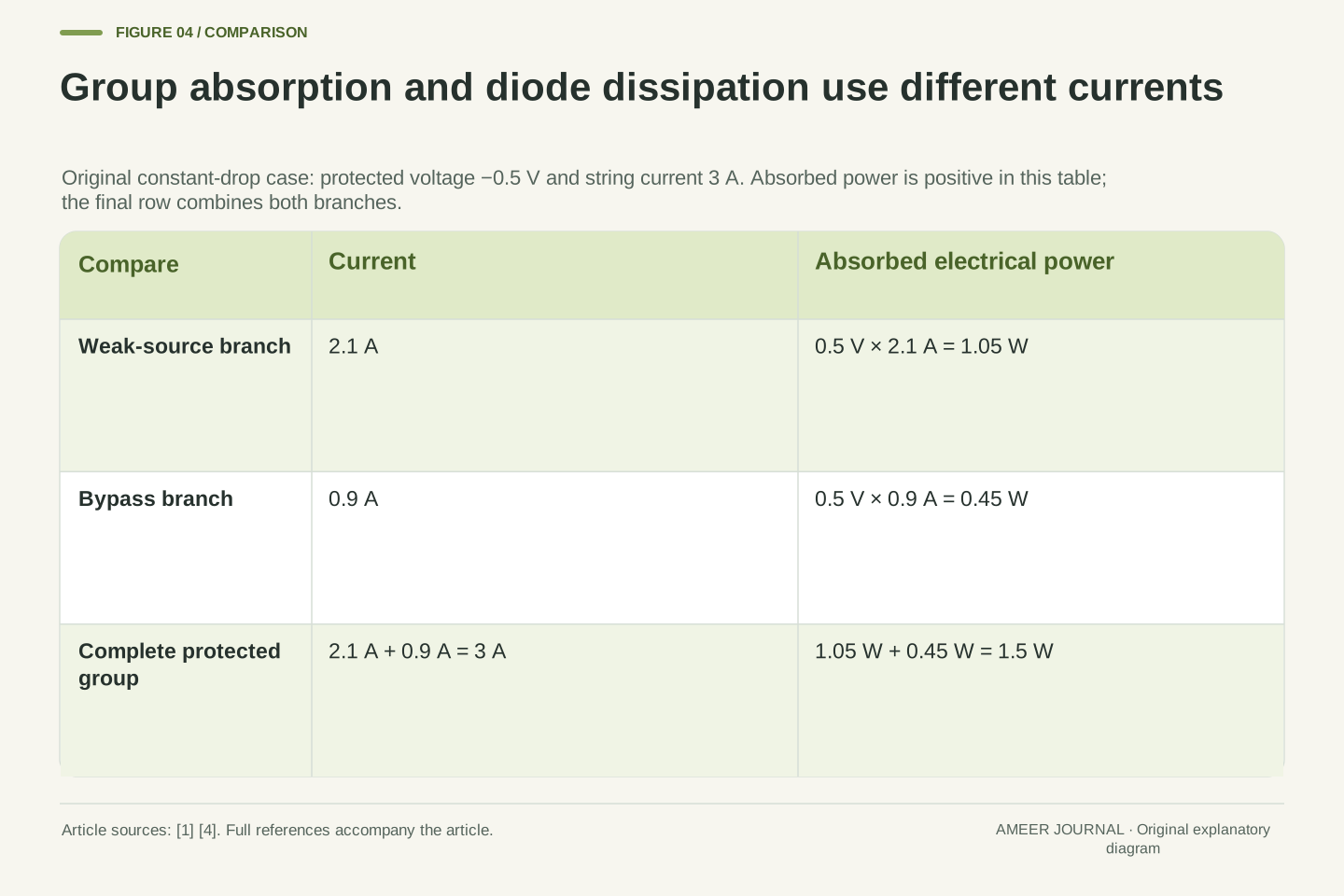
The weak source must now satisfy ten volts minus five volts per ampere times its current equals negative half a volt. Its current is 2.1 amperes. At a three-ampere string current, the bypass therefore carries 0.9 ampere. The entire protected group absorbs 1.5 watts, but only 0.45 watt belongs to the bypass branch. The source branch absorbs the remaining 1.05 watts.
Each bright group still supplies six volts, so the string voltage becomes 11.5 volts and output becomes 34.5 watts. Multiplying the whole three-ampere current by the half-volt drop correctly finds the group's total absorption. Calling all of that diode heating would use the wrong branch current. The two calculations answer different questions.
Define a separate constant-drop bypass model with V_w≥−0.5 V, D≥0 and (V_w+0.5 V)D=0. The blocking relation remains J=I and V_w=(10−5i) V, valid through i=2.1. On the conducting branch, J=2.1 A and D=I−2.1 A. The voltage-drop mechanism is source-supported [4]; the numerical constant and piecewise rule are stipulated.
At I=3 A, the weak-source delivered power is (−0.5 V)(2.1 A)=−1.05 W, while the bypass delivered power is (−0.5 V)(0.9 A)=−0.45 W. Their sum is −1.5 W, equal to V_w I. Thus diode dissipation is 0.45 W in this model; the entire group's net electrical absorption is 1.5 W. The difference is not a rounding error.
The two bright groups deliver 36 W together, leaving 34.5 W at the string terminals. On this conducting branch, V_string=(23.5−4i) V. Its positive-output domain ends at i=47/8. No actual thermal distribution follows from these port powers, and a constant-drop approximation supplies neither a component rating nor a universal junction characteristic.
One current branch can have a local best point while another is better
Return to the ideal zero-drop construction. On the lower-current branch, the best output occurs at about 1.889 amperes and seventeen volts, giving about 32.111 watts. The bypass is inactive there because the current is below two amperes. Raising current to the boundary reduces power slightly to thirty-two watts, even though it increases the current.
On the bypass-conducting branch, the best point is three amperes and twelve volts, giving thirty-six watts. This is the overall maximum of our declared curve. Its voltage is lower than seventeen volts, yet its current is high enough to give more power. A voltage-only comparison would miss that change in the product.
Both answers come from checking each branch's interior and endpoints. The Technical version shows that calculation. A real controller's ability to find or remain at a maximum is a separate question. Our two peaks describe the assigned steady curve; they do not report how any inverter searches it or how much energy a roof produces during a day.
On the first ideal branch, P/(1 W)=34i−9i², whose stationary point is i=17/9, inside [0,2]. There V_string=17 V and P=289/9 W≈32.1111 W. On the second branch, P/(1 W)=24i−4i², whose stationary point i=3 lies inside [2,6] and gives V_string=12 V and P=36 W.
The boundaries i=0,2,6 give 0 W,32 W,0 W. Comparing all valid stationary points and boundaries establishes 36 W as the global maximum. The first stationary point remains a local maximum, separated from the higher peak by the branch join. Multiple power regions are consistent with the qualitative bypass discussion [1][4], but these particular vertices are derived solely from our assigned equations.
For the separate half-volt model, the conducting-branch stationary point is i=47/16=2.9375, with V_string=47/4 V=11.75 V and P=2209/64 W=34.515625 W. Its other branch and boundaries are lower. Therefore the earlier fixed-current value of 34.5 W is not that model's exact maximum. A specified current point and an optimized point must remain distinct.
Separate component maxima do not automatically coexist in a string
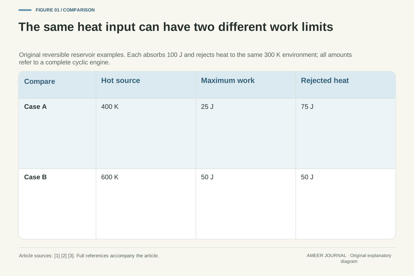
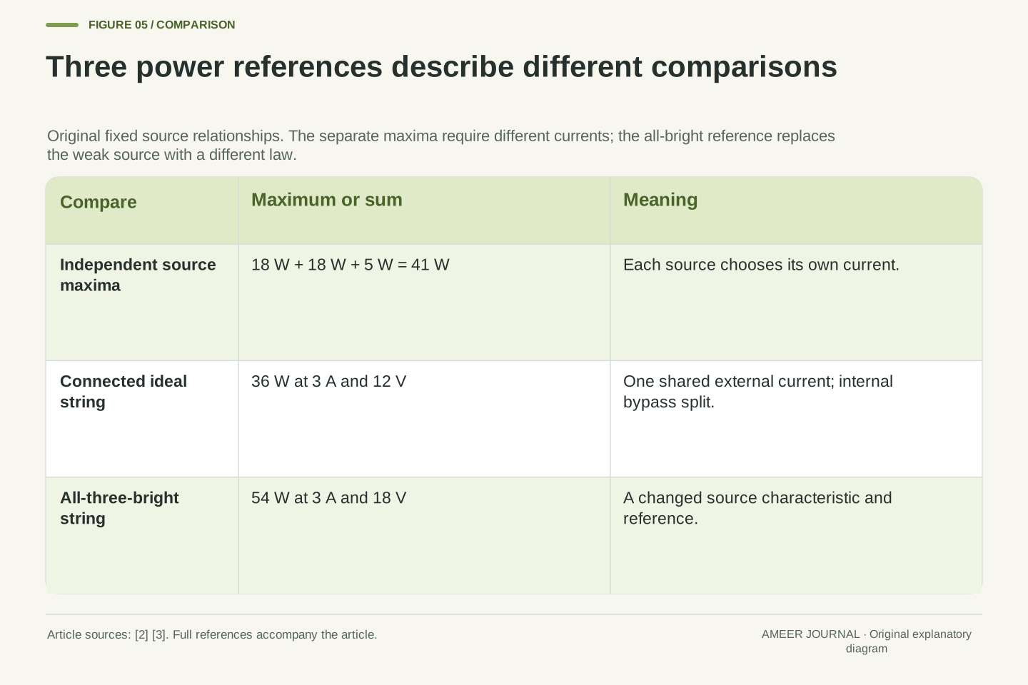
Consider each source on its own, before imposing the shared-current string. Each bright group has a maximum of eighteen watts at three amperes. The weak source has a maximum of five watts at one ampere. Adding those three separate maxima gives forty-one watts, but it combines operating points that require different currents.
The ideal connected string instead has a maximum of thirty-six watts. The five-watt gap is a mismatch between the sum of separate best outputs and the best compatible string output. PVsyst defines a mismatch reference in this way, while Sandia explains why shared current or voltage can prevent components from all operating at their individual maxima [2][3].
Another reference gives another gap. Replace Weak with a third bright group and the new three-bright string can provide fifty-four watts. That changes a source relationship; it is not the same forty-one-watt reference. Saying that the shaded construction lost five watts and saying it is eighteen watts below the all-bright construction can both be correct, provided the comparison is named.
A standalone bright group has power i(12−2i) W and maximum 18 W at i=3. The standalone weak source has power j(10−5j) W and maximum 5 W at j=1. Their separate maxima sum to 18 W+18 W+5 W=41 W. The maximizing currents differ, so this sum is not an attainable point of the declared series interconnection.
The connected ideal maximum is 36 W, giving a 5 W difference from that 41 W reference. This is the relevant distinction in the source definition of mismatch [3]. More generally, maximizing a sum over one shared current need not equal summing maxima obtained with independently chosen currents. A bypass changes the available two-terminal characteristic but does not eliminate every compatibility constraint [2].
For a different reference, replace the weak law by the bright law. Then V_string=(36−6i) V and the maximum is 54 W at i=3. The original ideal result is 36/54=2/3 of that altered reference. This fraction belongs to the stipulated comparison, not to a universal rule that one shaded group always removes one-third of available power.
Counting the affected groups cannot determine one universal power fraction
Keep the same arrangement of three groups and the same ideal bypass, but change the weak source's rule. Let it start at fourteen volts instead of ten, still losing five volts per ampere through its source branch. This is another assigned source characteristic. We are not claiming that a particular shadow area produces that change.
The bypass now remains inactive until 2.8 amperes. Below that transition, the string voltage follows thirty-eight minus nine times the current in amperes. Its best point is about 2.111 amperes and nineteen volts, giving about 40.111 watts. The bypass is inactive at that point. The separate bypass-conducting branch still reaches only thirty-six watts.
The new overall maximum is therefore about 40.111 watts, even though the number of groups and bypass paths has not changed. The first construction preferred the bypass-conducting peak; this one prefers the other peak. PVsyst's shading discussion also warns that an assumed retained fraction depends on the electrical arrangement and conditions [4]. A count of affected groups leaves out the needed curves.
Change only the original weak-source law to V_w=(14−5j) V, retaining both bright laws and the ideal bypass. The transition is j=i=14/5=2.8. The string characteristic becomes (38−9i) V for 0≤i≤14/5, followed by (24−4i) V for 14/5≤i≤6. The two pieces meet at 12.8 V.
The first power branch has a valid stationary point i=19/9, V_string=19 V and P=361/9 W≈40.1111 W. Since 19/9<14/5, D=0 there. The second branch's maximum is still 36 W at i=3. Comparing the join and outer endpoints confirms that 361/9 W is the new global maximum, with the bypass inactive.
Relative to the separate three-bright reference, the fraction is (361/9)/54=361/486≈0.7428, rather than 2/3. This is a mathematical counterexample to determining the fraction from group count alone. It is not a shading-response fit or a claim that equal shadows produce these two source laws. The primary shading discussion supplies the broader dependence on interconnection and illumination conditions [4].
An output constraint can exclude the curve’s best point
A maximum describes the best point on the allowed curve. It does not show that every connected system can use that point. PVsyst discusses how an inverter's minimum operating voltage can limit access to a shaded string's maximum [4]. We can examine the same kind of restriction without assigning a specification to any real inverter.
Return to the original ideal construction and require the string voltage to be at least sixteen volts. Because its voltage falls as current rises, this permits only currents from zero to two amperes. The thirty-six-watt point at twelve volts is outside that allowed range. The best remaining point is seventeen volts and about 1.889 amperes, giving about 32.111 watts.
Notice that the best permitted point is above the sixteen-volt boundary, not exactly on it. It is the earlier local peak. A voltage limit does not always force the optimum onto the limit itself. We must compare the points that remain available, rather than assuming that the unconstrained maximum or the boundary will automatically be selected.
Impose the original ideal-model constraint V_string≥16 V. The complete voltage curve is strictly decreasing, and V_string=16 V at i=2, so the feasible domain is 0≤i≤2. The unconstrained global point i=3,V_string=12 V is excluded. This is an analytic operating-window restriction, not an implementation of an inverter controller.
On the feasible interval, the valid stationary point i=17/9 gives 289/9 W. The endpoints give 0 W and 32 W, so the constrained maximum occurs at 17 V, strictly above the 16 V lower bound. This distinction avoids generalizing a source-specific boundary-intersection description into a universal optimization rule [4].
The restriction changes the set of available operating points without changing any component law or the internal conservation equations. A controller's actual voltage range, current limits and dynamic behavior would be additional information. Our result proves only the best value within the declared static constraint; it does not assert that a real controller attains it or follows either power peak during changing weather.
Keep the protected boundary, branch currents and power reference together
When reading a bypass explanation, first identify what the diode spans: one cell, a group of cells or a larger two-terminal unit. Real protected groups can contain cells with different voltages, as the PVEducation discussion explains [1]. A clamp across the group does not reveal every internal cell voltage. Zero net group power also does not prove that every cell inside it has zero power.
Next distinguish the string current from the current in each parallel branch. Use the declared source relationship and diode rule to resolve the split, then add group voltages at that same external current. For a power comparison, state whether the reference is a fixed operating point, the connected string maximum, separate component maxima or a different all-bright construction.
Finally keep any output constraint attached to the result. In our original example, three amperes means a two-plus-one internal split and thirty-six watts only under the ideal bypass law. The half-volt model and the sixteen-volt operating constraint give different answers for different reasons. Those named assumptions make the explanation reproducible without turning a simplified circuit into a claim about a particular installed panel.
A reproducible record needs the protected-group boundary, terminal polarity, branch-current references, source characteristics, bypass law and output constraints. The group-versus-cell distinction matters because a real bypass often spans several cells [1][3]. Clamping the aggregate voltage does not determine individual reverse bias, heat generation or safe temperature. Those questions require an internal model and appropriate component evidence.
For the original ideal point, retain I=3 A,J=2 A,D=1 A,V_w=0 and V_string=12 V. For the half-volt point at the same string current, retain J=2.1 A,D=0.9 A,V_w=−0.5 V and V_string=11.5 V. The source and diode port powers then reproduce the full string balance without assigning the entire group loss to one branch.
Name the optimization domain and reference before reporting a maximum or loss. The 36 W connected maximum, 41 W independent-component sum, 54 W all-bright reference and 289/9 W voltage-constrained maximum answer different questions. The useful outcome is a complete chain from topology and constitutive assumptions to current division and power, with actual hardware behavior left to the evidence that describes it.

Sources & further reading
Explore the references behind this guide. External pages may change after our review.
- Bypass Diodes | PVEducationPVEducation · Accessed 7 Nov 2026
- DC Array IV – PV Performance Modeling Collaborative (PVPMC)Sandia National Laboratories PV Performance Modeling Collaborative · Accessed 7 Nov 2026
- Array Mismatch Losses - PVsyst documentationPVsyst · Accessed 7 Nov 2026
- Effect of by-pass diodes and partial shading - PVsyst documentationPVsyst · Accessed 7 Nov 2026
Article updated 7 Nov 2026.
Found something we should revisit?
Good explanations get better with thoughtful feedback.