What you’ll take away
- An intact fibre can lose guided optical power at a bend without first fracturing.
- Core, cladding and protective coating have different roles.
- Critical incidence is measured from the boundary normal; it is not the external launch angle.
- A guided wave can extend into cladding, so a ray cartoon is not a complete field picture.
- Sequential power transmission factors multiply; optical power is not a percentage of internet speed.
An unbroken cable can still guide less light
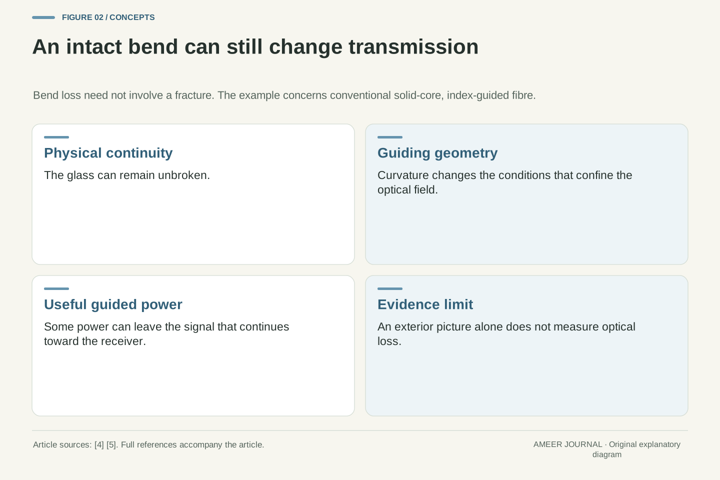
A fibre cable does not have to snap before its optical signal weakens. A sufficiently demanding bend can change how light stays guided, allowing some power to leave the useful guided signal. The Fiber Optic Association describes this bend sensitivity and explains that the result depends on the fibre and cable design [5]. That answers an everyday puzzle: 'The cable still looks intact' and 'less light reaches the receiver' can both be true. The outside appearance alone does not settle the optical question.
We will build the explanation from three layers, one carefully labeled angle example and a small power calculation. The scope is conventional solid-core fibre guided by the difference between the core's and cladding's optical properties. Special fibre designs exist, including hollow-core types, so the explanation is not a rule for every product called optical fibre [4]. All numbers below are invented teaching examples. No cable was bent or measured, and there is no need to open a connector, handle bare glass or look into a fibre end. The useful skill is reading a diagram and asking which guiding condition changed.
Optical continuity is not equivalent to unchanged transmission. An intact solid-core fibre can acquire additional bend loss because its guiding geometry changes, coupling power out of the useful guided field without requiring a fracture [5]. Mechanical damage is another possible problem, but it is not a necessary intermediate step in this mechanism. That distinction matters when interpreting an explanation or a specification: a drawing of an unbroken strand does not establish that its attenuation is unchanged.
This article treats conventional index-guided solid-core fibre and uses a locally planar boundary and a step-index ray model where stated. It does not generalize that model to every specialty architecture; hollow-core fibres, for example, need a different account [4]. The original numerical examples are hypothetical and are not a simulation or measurement of a real cable. We will separate material layers, reference directions, wave confinement and link-level power accounting. Those separations make it possible to explain bend loss without claiming that the fibre is a hollow mirrored pipe or that every photon follows a drawn zigzag.
Core, cladding and coating do different jobs
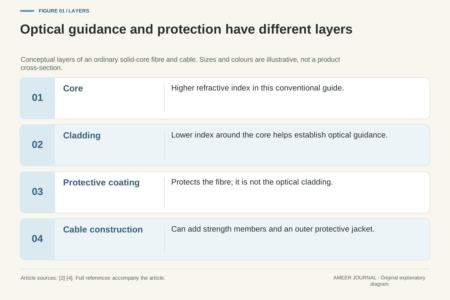
Picture a cross-section with a central core, cladding around it, and a protective coating outside. For the ordinary fibre described here, the core has a higher refractive index than the cladding. This difference helps guide light. The coating protects the glass, while the larger cable can add strength members and an outer jacket [2][4]. Cladding is therefore not just another name for the plastic covering you might see from outside. Its optical role is part of the guide itself.
A useful paper sketch gives each layer a job, rather than only a colour. Label the core 'higher index', the cladding 'lower index', and the coating 'protection'. Do not label the cladding 'silver mirror': ordinary guidance here does not need a metal lining. Nor should the drawing look like an empty tunnel with light travelling through air. Its core is solid material. The sketch leaves out true dimensions and many cable details, but it preserves the relationship that matters. If the protective jacket changes, that does not by itself tell us the two glass regions have changed their refractive indices.
Distinguish the optical structure from the protective structure. The central core and surrounding cladding establish a refractive-index profile, with a higher-index core in this conventional case. The primary coating protects the fibre; a cable construction can add further protective layers, strength members and a jacket [2][4]. The boundary relevant to the basic guiding argument is therefore the core–cladding interface, not automatically the outer surface of the finished cable.
For the following calculations, assume a step-index profile: one uniform core index and one lower uniform cladding index, separated by an ideal interface. This assumption simplifies the geometry; it is not a claim that all communication fibres have that profile. A schematic should show distinct optical and protective roles without copying a product cross-section or suggesting measured dimensions. Replacing the familiar tube-of-mirrors image with these labeled regions also prevents a category error. Protective material can influence how a cable tolerates stress, but the explanation of total internal reflection concerns optical indices and incidence at a boundary, not reflective paint on a hollow channel.
First decide what the angle is measured from
Refractive index describes how light travels in a material compared with vacuum; a higher value corresponds to a lower light phase speed in that material [4]. At a boundary between materials, the direction of a transmitted ray can change. The important angle in the usual refraction rule is measured from the normal: an imaginary line drawn at right angles to the surface [1]. 'Normal' here names a direction, not a judgment about whether the fibre is behaving normally.
Draw a short straight boundary on paper and then a line perpendicular to it. A ray almost running along the boundary makes a large angle with that perpendicular line. This can feel backwards if you first measured its small angle from the boundary itself. Both measurements describe the same ray, but they add to ninety degrees. A statement such as 'the angle must be large' is incomplete until the reference line is named. For a curved boundary, use the local normal at the point being considered. Keeping that small detail explicit prevents the most common apparent contradiction in simple fibre explanations.
The refractive index n is related to phase velocity by n = c/v, where c is the vacuum speed and v is phase velocity in the material [4]. Do not substitute that phase-velocity definition directly for every pulse-delay calculation in a dispersive guide. The boundary argument uses Snell's law, n₁ sin θ₁ = n₂ sin θ₂. Both angles are measured from the interface normal, and the source's geometry explicitly identifies that reference [1].
For a locally planar boundary, the normal is perpendicular to the interface. An incidence angle of eighty degrees from the normal is ten degrees from the boundary. Omitting the reference can therefore reverse the apparent direction of an inequality without changing the physical ray. At a curved interface, the relevant normal varies with position. These conventions matter before any numerical calculation: one must identify the incident medium, the second medium and the local normal. A fibre-axis angle, a wall-incidence angle and an external launch angle are not interchangeable labels even when a simplified diagram lets us relate them.
A worked example: eighty degrees and seventy degrees
For total internal reflection in the ideal boundary model, light must approach from the higher-index side. Its angle from the normal must also be greater than the critical angle [1]. Below that threshold, a transmitted ray into the second material is possible; some reflection can still occur. The threshold is therefore not the point where reflection first appears. It marks the change to total internal reflection under the stated ideal conditions.
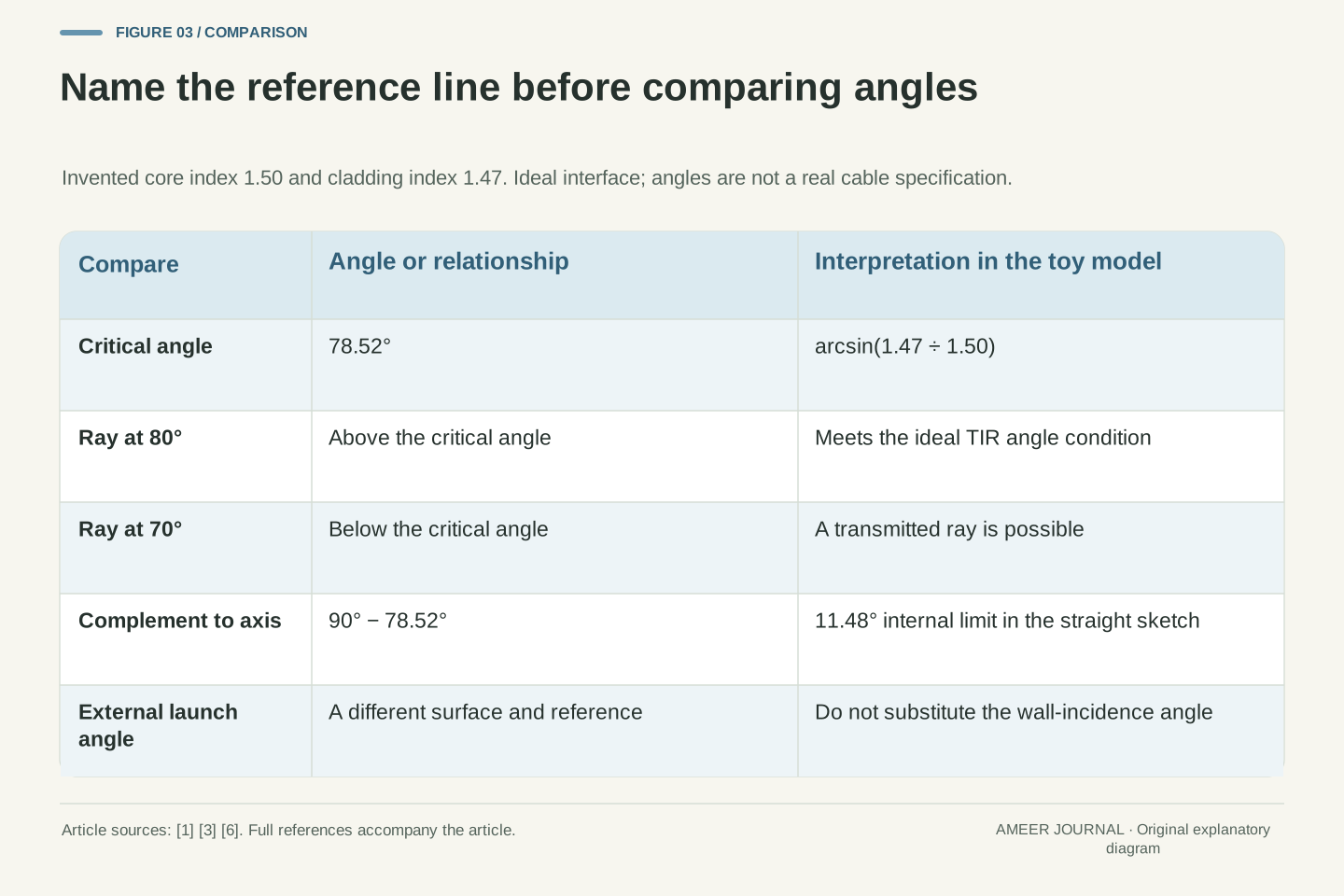
Take invented values of 1.50 for the core index and 1.47 for the cladding. Divide 1.47 by 1.50 to get 0.98. The angle whose sine is 0.98 is about 78.52 degrees, giving the critical angle from the normal. An eighty-degree ray exceeds it and meets the angle condition. A seventy-degree ray does not. These numbers describe an ideal interface, not a purchased cable. Reversing the materials would also change the answer: the higher-to-lower-index condition cannot be ignored. This small example explains why 'light is inside glass' is not enough to prove it will remain guided.
At the critical condition for n₁ > n₂, the limiting refracted ray lies along the interface: θ₂ = 90°. Snell's law then gives sin θc = n₂/n₁, hence θc = arcsin(n₂/n₁) [1]. For incidence strictly above θc, the ideal lossless dielectric-interface model has total internal reflection rather than a propagating transmitted ray crossing into the second medium. This statement should not be extended to zero electromagnetic field on the second side or to zero loss along an actual fibre.
Using hypothetical ncore = 1.50 and ncladding = 1.47 gives θc = arcsin(0.98) = 78.5217°, approximately. A ray incident from the core at 80° satisfies the inequality; one at 70° does not. The latter can have both reflected and transmitted components. These are normal-referenced angles, with the interface treated locally as planar. The example fixes the index ordering and omits absorption, imperfections and finite-guide effects. It demonstrates an angular criterion, not the attenuation, mode count or minimum permissible bend radius of a real manufactured fibre.
The angle at the entrance is a different angle
For a straight-sided sketch, the eighty-degree wall-incidence ray is ten degrees from the fibre's long direction. The critical angle of 78.52 degrees corresponds to about 11.48 degrees from that direction. Thus a large angle from the wall's normal can mean a small angle from the fibre axis. This is why two descriptions can seem to disagree when one says 'large angle' and the other says 'nearly along the fibre'. They may simply be using different reference lines.
Now add the entrance face. A ray approaching from outside meets a different surface and can change direction as it enters. Its outside launch angle is not automatically the same as its internal angle. Fibre specifications use numerical aperture to describe an acceptance range, but that is not just the wall's critical angle renamed [3]. The UNSW teaching model shows that a small index difference restricts which ray directions remain guided [6]. Our calculation concerns an ideal straight step-index sketch, not every possible launch into every fibre. It is a way to keep three angles separate before asking a real specification what conditions apply.
In a straight meridional-ray sketch, the fibre axis is parallel to the side boundary. Consequently, an 80° normal-referenced wall-incidence angle corresponds to 10° from the axis. The limiting complement for the invented indices is 90° − 78.5217° = 11.4783°. That internal geometric relationship explains why rays closer to the axis can satisfy a large normal-referenced incidence criterion. It does not yet specify the external acceptance angle.
At the entrance face, refraction relates the launch direction in the external medium to the internal ray direction. Numerical aperture describes an acceptance property, with the surrounding medium and index profile relevant to its interpretation [3]. A close core–cladding index pairing restricts guided directions in the simplified ray picture discussed by UNSW [6]. This section deliberately does not turn the complement into an external launch specification. Real coupling also concerns the optical field and guide design. Before comparing two angle values, name their surfaces, reference lines and media; otherwise a valid number can be attached to the wrong physical question.
The zigzag drawing is useful, but it is not the whole wave
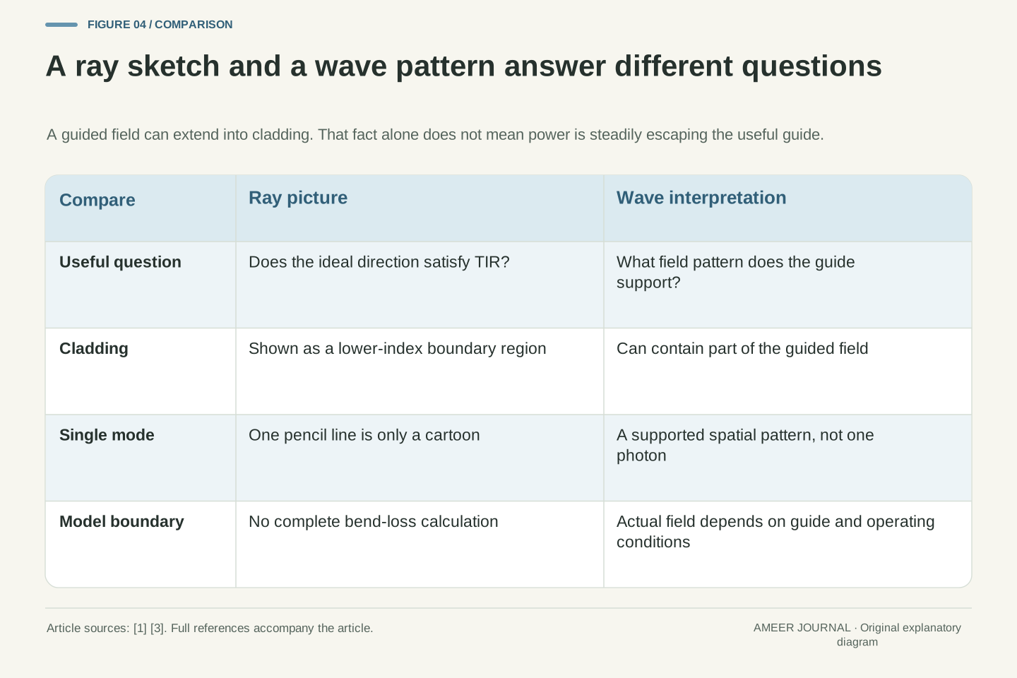
A ray drawing helps explain directions, but light is an electromagnetic wave. In a guided wave pattern, some of the field can extend into the cladding. Corning's glossary explicitly explains that the light distribution in single-mode fibre includes both core and cladding [3]. That does not mean the cladding is useless or that all of that light is escaping. A field extending outside the core is different from power steadily leaving the useful guided signal.
Think of the ray picture as a map for one question: can this ideal direction meet the reflection condition? It cannot answer every question about the size or shape of the guided field. In particular, 'single-mode' should not be read as 'one photon follows one pencil-thin route'. A mode describes an allowed wave pattern in the guide. The core's physical size and the spread of that pattern are related but are not identical labels [3]. Keeping both ideas available lets us use the simple angle calculation without pretending it is a complete portrait of light inside a real fibre.
The geometrical ray model is not a complete modal solution. A guided mode is a propagating electromagnetic field pattern, with its transverse distribution determined by the guide. In a conventional single-mode fibre, the distribution extends through the core and into the cladding; mode-field diameter describes that distribution rather than merely repeating the physical core diameter [3]. The existence of cladding field is compatible with guidance. It is not, by itself, evidence of continuous outward radiation loss.
Likewise, total internal reflection at an ideal interface does not mean that the electromagnetic field is identically zero on the lower-index side. The ray model omits that detail while remaining useful for its limited angular question. Single-mode operation concerns supported spatial modes in an operating regime, not the number of photons, data bits or wavelengths that could be present. A drawing of one straight line or one zigzag cannot establish the actual field distribution. This is the point where one should stop treating the ray sketch as a literal trajectory and retain the wave interpretation alongside it.
A bend changes the guide, not just the cable’s appearance
Return to the bend. In the simple ray picture, curving the boundary changes the local surface direction and therefore the normal that defines incidence. A ray that fits the straight-guide sketch cannot be assumed to meet exactly the same condition everywhere along a curved guide. The wave description is more complete: the bend changes confinement, and some guided power can be lost. The Fiber Optic Association explains bend loss in terms of power no longer remaining guided in the useful core region [5].
This does not mean that every gentle curve produces a visible failure, or that one bend angle alone determines the result. A broad curve and a tight turn can change direction by the same total amount while having very different radii. Fibre design, wavelength and cable construction also matter [5]. The original 78.52-degree calculation supplies no universal bend radius because it contains no cable dimensions or wave-field solution. That is an important boundary on what our example proves. It explains why geometry matters; it does not turn a paper angle into a real installation limit.
Macroscopic curvature changes the guiding geometry. A local-ray account can illustrate the changing interface normal, but calculating bend attenuation requires more than transferring a straight-guide critical angle to a curved drawing. In the wave picture, curvature affects confinement and can couple power into radiation or other non-useful fields. The association's reference identifies fibre type, index-related design, wavelength and cable construction as relevant factors [5]. None of those effects requires the glass to have broken first.
Separate bend angle from bend radius. Two routes can each turn through ninety degrees while one uses a long gradual arc and the other a compact corner. Those are not equivalent guiding conditions. The toy indices alone cannot predict a loss in decibels or establish a mechanical limit: they specify neither guide dimensions nor the full index profile, wavelength, bend geometry or field distribution. The useful deduction is conditional. Changing geometry can increase optical loss in an intact guide; whether a particular installed cable has that problem requires evidence about the actual cable and link, not this schematic.
Bend-insensitive does not mean bend-proof
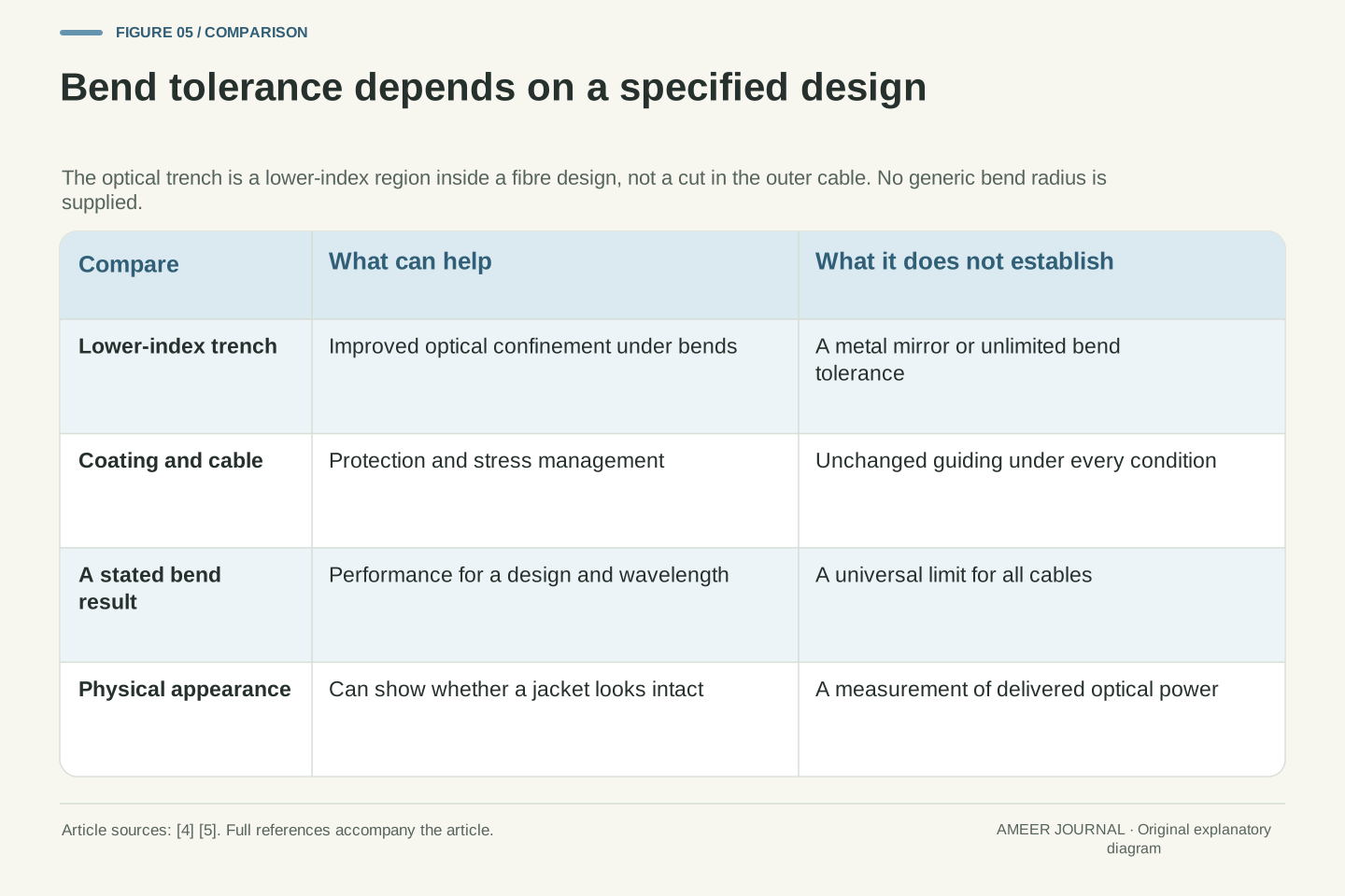
Some fibre designs improve bend tolerance by including an extra lower-index region around the core, often called a trench. This is an optical feature inside the fibre's index profile, not a groove cut into the outside of a finished cable. The design helps confine light under bending conditions that would cause more loss in another fibre [5]. Protective coatings and cable construction also matter, but they play different roles from that internal optical profile.
The word 'insensitive' is a comparison under specified conditions, not a promise that any knot or crushing force is harmless. A useful claim names the design, wavelength, bend geometry and allowed loss. Mechanical handling limits and optical loss limits are related practical concerns, but one number does not automatically replace the other. The FOA cautions against copying dramatic tight-bend demonstrations and points users to manufacturers for product-specific guidance [4]. Here, the scientific conclusion is simply that the guide can be engineered to tolerate some bends better. We have not ranked products or supplied a safe radius for an unidentified cable.
Trench-assisted designs introduce a deliberately lower-index annular region into the fibre profile. The additional structure improves confinement and can reduce bend-induced loss compared with another design under comparable conditions [5]. The term trench denotes an optical-index feature in the glass, not a mechanical cut in the cable jacket. It is therefore inaccurate to explain bend tolerance solely as stronger plastic protection or to describe the improvement as a perfect reflecting metal wall.
Treat bend-insensitive as a performance description with conditions. A meaningful comparison needs the operating wavelength, fibre design, curvature and acceptable excess loss, while practical installation also has mechanical constraints. The present article does not reproduce historical standards tables or promote their example radii as current universal limits. FOA's basic reference explicitly discourages imitating extreme demonstrations and directs product-specific handling questions to the manufacturer [4]. Better optical tolerance does not prove unlimited mechanical durability, universal compatibility or zero attenuation. Those are separate claims requiring their own evidence. The mechanism explains why a redesign can help without establishing how far an unknown cable may be bent.
A power example: twenty percent and fifty percent do not add
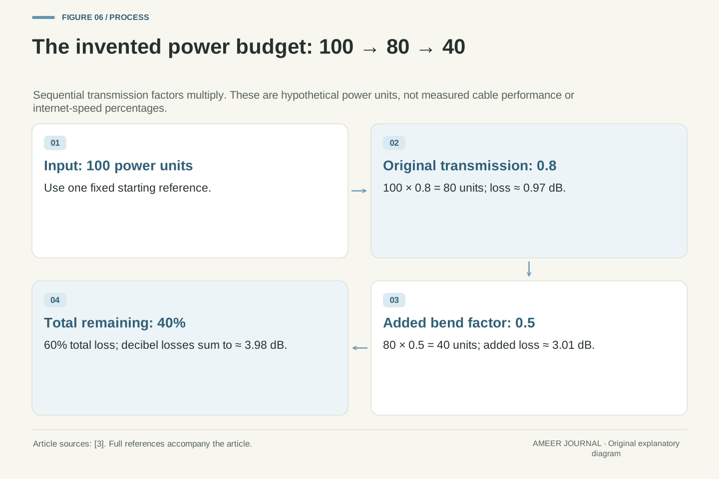
Imagine a fictional link receiving one hundred units of optical power and delivering eighty. Its existing losses have removed twenty percent. Now suppose a new bend transmits only half of the power that would otherwise arrive, with everything else unchanged. Half of eighty is forty. The final output is forty percent of the original input, so the total loss is sixty percent. Adding twenty percent and fifty percent to claim seventy percent would use two different starting amounts as though they were the same.
This is only arithmetic for invented transmission factors; real bends do not all remove half the power. Engineers often describe power loss in decibels, using a logarithm of the input-to-output power ratio [3]. In this example, the original loss is about 0.97 dB, the added loss about 3.01 dB, and their sum about 3.98 dB. Those decibel losses add because their underlying power ratios multiply. None of these numbers tells us that the internet connection runs at forty percent of its former speed. Optical power, successful signal detection and data throughput are different quantities.
Define an entirely hypothetical power budget with input P₀ = 100 arbitrary units and initial output P₁ = 80. The original transmission factor is 0.8. Let an additional bend introduce a factor of 0.5 relative to that original delivered power, with the rest of the model fixed. Then P₂ = 100 × 0.8 × 0.5 = 40. The remaining fraction is 0.4 and the aggregate lost fraction is 0.6. The two percentage losses cannot be added because their reference powers differ.
Using positive loss L = 10 log₁₀(Pin/Pout), consistent with power-ratio attenuation in decibels [3], the first stage is 10 log₁₀(100/80) = 0.9691 dB. The bend adds 10 log₁₀(80/40) = 3.0103 dB. Total loss is 3.9794 dB, agreeing with 10 log₁₀(100/40). The calculation uses power ratios, so the factor is ten rather than the field-amplitude factor twenty. This is not a measured bend penalty, a receiver-margin calculation or a throughput model. Its purpose is to preserve the reference quantity when combining sequential losses.
Ask whether the claim concerns power, timing or geometry
A weak signal and a spread-out pulse are not the same problem. Attenuation concerns reduced optical power between locations. Dispersion concerns how a pulse spreads in time [3]. In a simplified multimode ray picture, different travel paths can produce different arrival times; UNSW uses that idea to explain pulse broadening [6]. Single-mode fibre removes that particular many-spatial-mode situation, but it does not make every possible kind of pulse spreading disappear [4]. A claim about low loss therefore does not automatically establish a claim about timing.
When you next read that a fibre 'keeps light inside', ask three precise questions. Which guide and layers are being described? From which line is each angle measured? Does the result concern retained power, pulse timing or a mechanical limit? Our invented indices answer one boundary-angle question. Our one-hundred-to-forty example answers one power-accounting question. Neither measures a real cable. The central result is now easier to state accurately: guidance depends on optical structure and geometry, so an intact bend can weaken the guided signal. Better bend tolerance changes the design's performance under stated conditions; it does not remove the need to state those conditions.
Keep attenuation separate from dispersion. Attenuation measures a reduction in optical power, whereas dispersion describes temporal spreading [3]. The multimode ray illustration can connect differing path lengths to arrival-time differences [6], but that is not a complete treatment of every fibre. Chromatic dispersion and polarization-related effects remain relevant even when multiple spatial modes are absent [3][4]. Neither low attenuation nor single-mode operation establishes unlimited bandwidth. These distinctions prevent a correct confinement explanation from acquiring an unsupported communication-performance conclusion.
A defensible reading of a fibre claim identifies the architecture, wavelength regime, geometry and reported quantity. A critical-angle derivation answers a local ideal-interface question. A bend-loss specification concerns a particular curved guide under stated conditions. A power budget combines transmission factors, while a dispersion account considers pulse evolution. These are connected descriptions, but they are not interchangeable measurements. The original calculations here provide no observed latency, link speed, installation radius or cable diagnosis. They support the narrower conclusion that an intact optical structure may guide less power after its geometry changes, and explain why improving bend confinement is an engineering problem rather than simply a promise that glass will not break.
Sources & further reading
Explore the references behind this guide. External pages may change after our review.
- Optical Society of America: Exploring the Science of Light - What is Optics?: Snell�s Law, Reflection, and RefractionFlorida State University / Optical Society of America education · Accessed 6 Nov 2026
- How It Works: Optical FiberCorning · Accessed 6 Nov 2026
- Optical Fiber Glossary of Terms | Optical Communications | CorningCorning · Accessed 6 Nov 2026
- The FOA Reference For Fiber Optics - Optical FiberThe Fiber Optic Association · Accessed 6 Nov 2026
- The FOA Reference For Fiber Optics - Bend Insensitive FiberThe Fiber Optic Association · Accessed 6 Nov 2026
- Optical fibres and cladding: Physclips - LightUniversity of New South Wales / School of Physics · Accessed 6 Nov 2026
Article updated 6 Nov 2026.
Found something we should revisit?
Good explanations get better with thoughtful feedback.