What you’ll take away
- Map complete routes across a stated boundary before adding heat-transfer rates.
- Conduction, convection and radiation can appear in sequence along one route.
- A reflective surface and a bulk insulating layer address different parts of the transfer problem.
- A component improvement must be weighted by its contribution to the original total.
- Rates, energy amounts and temperature histories require different supporting information.
Start with the warm side and the cool side
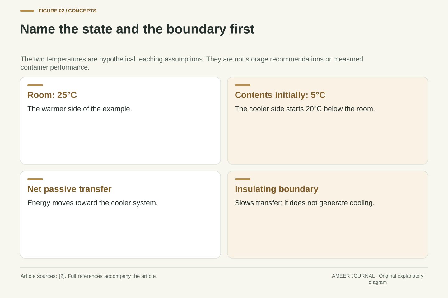
Picture a closed, insulated box sitting in a room. For this imaginary example, the room is at 25°C and an object inside starts at 5°C. Those are teaching assumptions, not measurements from a product test or recommendations for storing food. The useful question is where energy can enter the cooler interior. NASA describes the natural direction of heat transfer between objects at different temperatures: from the warmer object toward the cooler one, until thermal equilibrium is reached [2]. Insulation changes how quickly that happens. It does not give the cool object an endless supply of cooling.
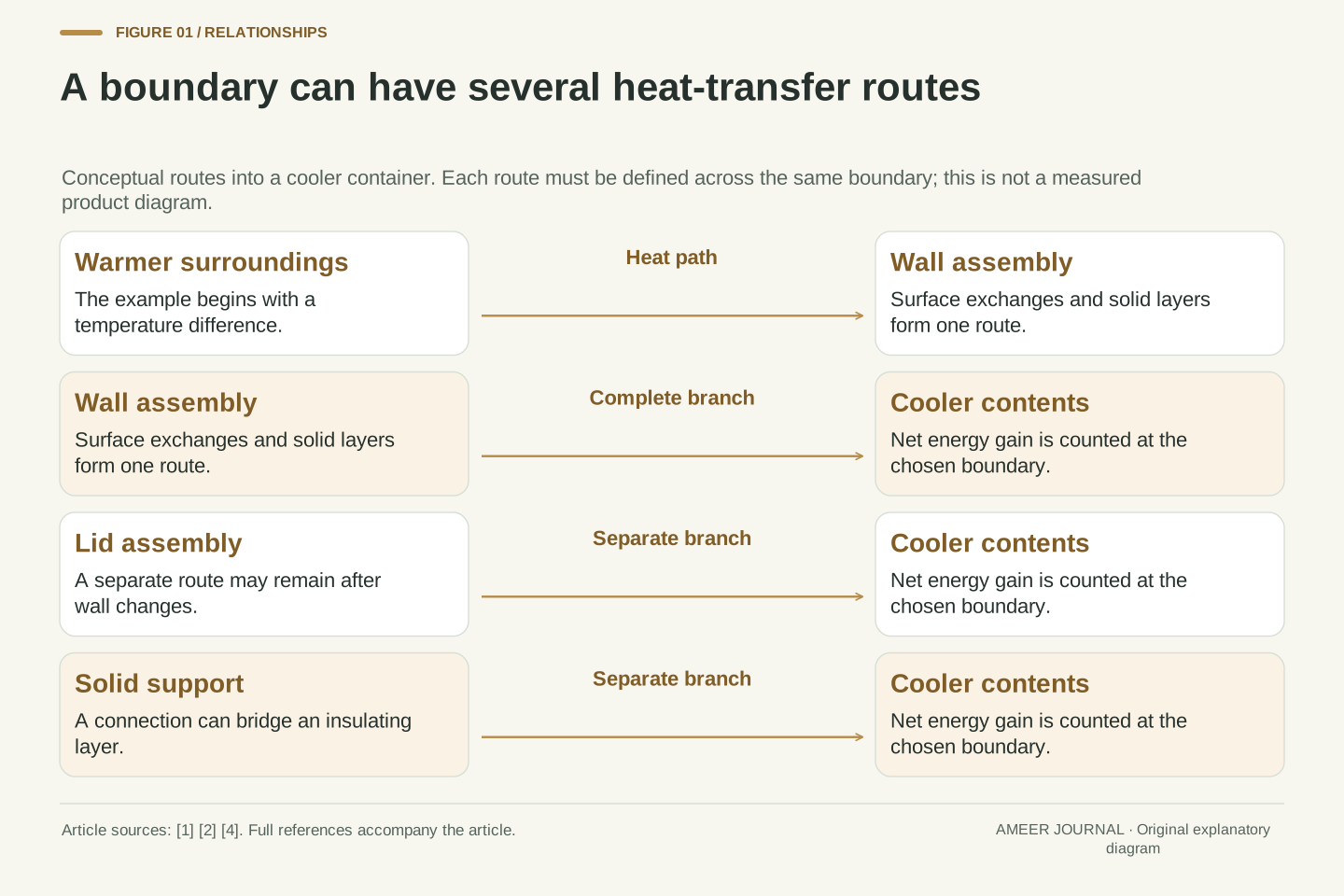
Draw a line around the part you want to study. We will put that line around the contents and inner space of the box. The wall, lid, supports and any opening can then be examined as routes across that boundary. NOAA identifies conduction, convection and radiation as heat-transfer mechanisms [1]. A real route may involve several of them in sequence. Looking for the routes first will help us avoid two mistakes: assuming a thick wall solves every problem, and counting the same travelling energy more than once.
Consider a hypothetical container with a 25°C surrounding room and contents initially at 5°C. Define the control volume as the contents plus the enclosed interior, and treat the room as an external thermal environment. The initial 20 K temperature difference provides a direction for passive net heat transfer into the cooler system. Thermal equilibrium concerns equality of temperature; an insulating boundary changes the approach toward equilibrium rather than establishing an independent cooling source [2]. These temperatures describe the example only and imply no safe-storage specification.
The analytical task is to identify complete transfer paths across the chosen control-volume boundary. The classification into conduction, convection and radiation describes mechanisms, not automatically independent accounting categories [1]. One joule may pass from room air to an outer surface, through a solid wall and into the interior through successive mechanisms. A defensible model must represent that route once. We will separate physical paths, discuss their resistances and then use an explicitly assumed short-interval energy budget. No conductance or cooling-time claim is attributed to a real container.
Keep temperature, energy and transfer rate separate
A temperature reading tells you about the state of something. It does not, by itself, tell you how much energy has crossed the box wall. NASA's heat-transfer explanation distinguishes a temperature change from the heat capacity that connects added energy with a temperature rise [2]. Two objects can begin at the same temperature and respond differently to the same incoming energy. You would need information about the contents and their thermal behaviour before turning a heat-gain figure into a prediction of their temperature.
We will use two different units in the example. A watt describes a rate: one joule transferred each second. A joule describes an amount of energy. If an assumed heat gain stays at 2 watts for 10 seconds, the amount gained is 20 joules. The time interval matters just as much as the rate. A label saying that a container has a low heat-transfer rate is incomplete unless its conditions are stated. A label saying that it kept something cool for a particular time also needs the starting temperatures and the contents.
Temperature, internal-energy change and heat-transfer rate are distinct quantities. Heat capacity provides a relationship between an energy input and a temperature change under specified conditions, while NASA's thermodynamic discussion also notes that process conditions matter [2]. A container model cannot predict a temperature history from a wall rating alone. It needs the thermal properties and amount of material in the control volume, its initial state and the boundary conditions. We do not assign an actual material heat capacity in this worked example.
Write the total heat-transfer rate as P and the transferred energy as Q. Power has SI units of watts, with 1 W = 1 J/s. Over an interval with a constant assumed rate, Q = P × Δt. For a changing rate, the contributions from successive intervals must instead be accumulated; one initial value cannot be extended indefinitely. A rise in the contents' temperature may reduce the driving temperature difference, so the later rate need not equal the initial rate. Keeping the rate calculation separate from the state calculation prevents an apparent insulation improvement from becoming an unsupported storage-time promise.
Conduction follows connected material
Conduction transfers energy through matter without requiring that the whole piece of material travel from one side to the other. NOAA uses the familiar example of energy moving along a metal spoon and notes that metals conduct heat effectively while air conducts it poorly [1]. In our imagined box, energy can move through the wall material, the lid and solid parts that join the inside to the outside. The mechanism is not limited to the largest surface. A smaller connecting piece may also matter if it offers an easier route.
The size and arrangement of a route matter as well as its material. The Building America guidance relates heat flow through a section to its area, the temperature difference and the thermal resistance of the assembly [4]. A larger area offers more places for energy to pass. Adding suitable resistance can slow a particular route, but a metal connection around that resistance is still a route. Think of drawing every solid connection on the box sketch before choosing which one deserves attention. A wall material's rating does not describe an unexamined lid or handle.
Conduction is energy transport through interacting matter. Bulk motion of the solid is not required; NOAA's metal-spoon example illustrates a temperature difference driving transfer along a connected object [1]. For container analysis, continuity of the material path matters. A wall panel, fastening point or structural connection can join regions at different temperatures. A low-resistance connection through an otherwise resistant boundary is a thermal bridge. Its contribution depends on geometry and material properties rather than on whether it is visually prominent.
The Building America heat-loss formulation makes the dependence on area, temperature difference and assembly resistance explicit [4]. In consistent SI notation, an idealized one-dimensional section with area-normalized resistance R″ has P = AΔT/R″. This is a model for the stated section and conditions, not a universal product rating. Increasing resistance in one branch reduces that branch's flow if the other assumptions are held fixed. Bridges introduce additional paths, and real three-dimensional heat spreading may require a more detailed model than separate uniform panels. A quoted material property therefore needs an identified assembly boundary.
Convection depends on the fluid and its movement
Air and water are fluids: they can move and change shape. Convection involves heat transfer associated with moving fluid. NOAA describes warmer air rising and cooler surrounding air taking its place in an atmospheric example [1]. In a container, air next to a surface may exchange energy with that surface and then move elsewhere. Air circulation inside the box and air movement outside it can therefore be part of the transfer route, even when the box itself stays still.
Some movement develops because of temperature-related density differences; other movement is forced by a fan or wind. The result depends on the situation, so simply writing 'air gap' does not establish how much insulation a space provides. Building America describes unwanted circulating air loops in gaps and explains why the arrangement of insulation and an air barrier matters [4]. For our paper model, distinguish still pockets of gas within a designed insulating structure from a large connected space where circulation can develop. Also distinguish circulation near a closed wall from air passing through an actual opening.
Convection combines transfer at a solid-fluid interface with energy transport by fluid motion. In a familiar natural-convection case, heating changes fluid density and buoyancy can drive circulation; NOAA illustrates this with warmer air rising relative to its surroundings [1]. Forced convection instead involves motion driven by an external influence such as a fan. The local transfer behaviour depends on the fluid, geometry, orientation, temperature conditions and flow. A statement that air is a poor conductor does not establish that any volume of air is an effective insulating layer.
Building America identifies convective loops and thermal bypasses associated with gaps and misaligned air barriers [4]. For our container, the external air film, wall assembly and internal air film can form successive parts of a transfer path. Fluid circulation within a sealed cavity changes transport inside that cavity; an opening can additionally carry energy with matter entering or leaving the control volume. Keeping those cases separate helps specify what a proposed seal, airflow change or insulating layer is intended to alter. No universal percentage reduction follows from the mechanism name alone.
Radiation does not need an air current
Radiation can carry energy across a gap without air flowing through it. NOAA describes radiative transfer as energy travelling by electromagnetic radiation [1]. This is a different route from conduction along a solid connection or energy carried by moving air. An empty-looking space therefore does not automatically stop every form of heat transfer. The surfaces facing the gap can exchange radiation, and their properties affect that exchange.
NASA's archived explanation of a vacuum bottle gives a useful combination: reducing the gas in the gap suppresses gas conduction and convection, while a reflective metallic coating helps limit radiative exchange [3]. Those are separate jobs. Removing the gas does not make radiation disappear, and a reflective surface does not remove a solid connection. In our imagined box, draw the radiation route between facing surfaces as well as the solid routes through supports. The drawing is a mechanism map, not proof that a particular coating or gap will deliver a claimed number of hours of cooling.
Thermal radiation transfers electromagnetic energy between surfaces and their surroundings without requiring a material carrier across the intervening space [1]. The net exchange depends on the temperatures, the radiative properties of the relevant surfaces and the geometry of their interaction. It must not be inferred solely from an object's visible colour. For the present model, a radiation path across a gap is physically distinct from gas conduction and from fluid circulation within that gap.
The vacuum-bottle explanation in NASA's archived Cosmicopia material explicitly separates suppression of gas conduction and convection from suppression of radiative exchange using a reflective coating [3]. An ideal empty gap removes the gas-mediated mechanisms across that gap, not conduction through the solid supports surrounding it. Nor does it remove radiation. This example is useful because it identifies which transport channel each design element addresses. It is not a measured performance specification for the container in this article, and we do not extend the archive's simplified descriptions of space temperatures or solar heating into quantitative claims.
Resistance and reflection solve different parts of the problem
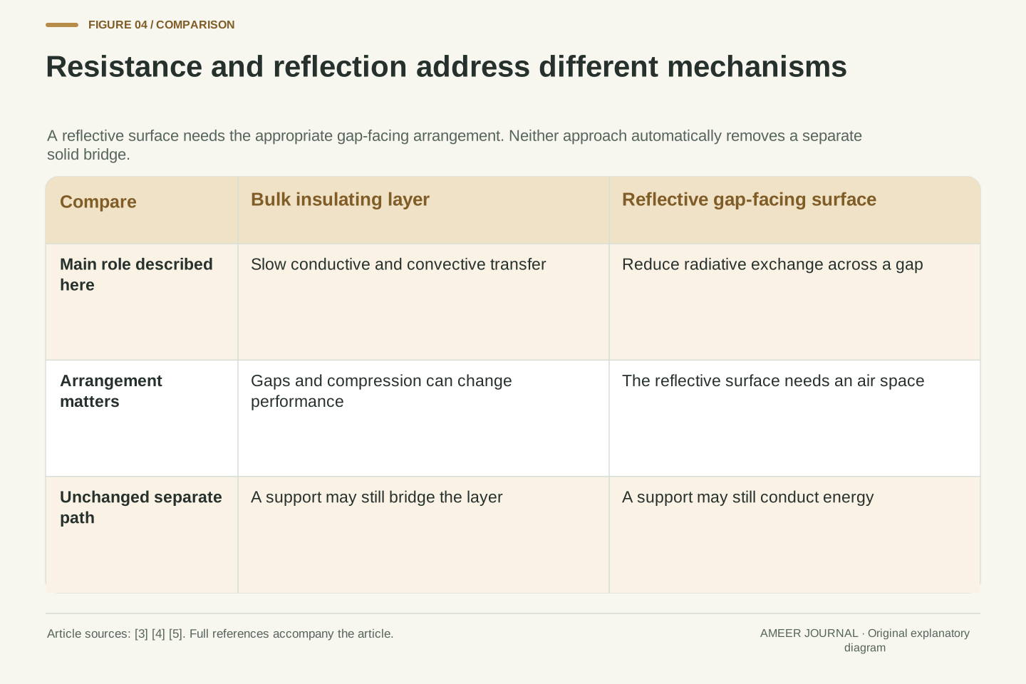
A bulky insulating layer and a reflective surface may both belong in a thermal design, but they do not perform the same task. DOE's Building Science Education material explains that common insulation reduces conductive and convective heat flow, while reflective systems reduce radiant heat gain. It also states an important condition: the reflective surface needs to face an air space to work as described [5]. The word 'shiny' by itself is not a complete insulation specification.
Imagine three proposals for our box. One improves the wall's insulating layer. Another changes a surface facing a gap. A third addresses a solid connection that bypasses the wall. Ask which route each proposal changes. You cannot add the claims together without checking whether they describe independent routes or different parts of the same route. Installation and arrangement also matter: Building America notes gaps, compression and misplaced insulation as reasons that an assembly can behave differently from a material's stated rating [4]. This is why the finished boundary deserves attention, not just a sample of its best-performing material.
Bulk insulation and a low-emittance reflective surface address different aspects of the heat-transfer network. DOE describes common insulation as slowing conductive and convective heat flow, whereas radiant barriers and reflective insulation reduce radiant heat gain under an appropriate air-space arrangement [5]. That arrangement is part of the boundary condition. A reflective surface pressed between solid layers cannot be credited with the same gap-facing radiative function merely because it has the same appearance.
A useful evaluation therefore specifies the intervention and the affected path: increase the resistance of a wall assembly, modify radiative exchange across a gap, or reduce a bridge through a structural connection. Building America's discussion of gaps, compression and air-barrier alignment shows why installed performance cannot be inferred from a nominal material rating alone [4]. These mechanisms can interact. For example, changing a surface temperature can change transfer elsewhere. Our later budget deliberately freezes the other branch rates so that one simple comparison can be calculated transparently; that simplification is not a claim that real assemblies always behave independently.
Do not count the same energy at every stage
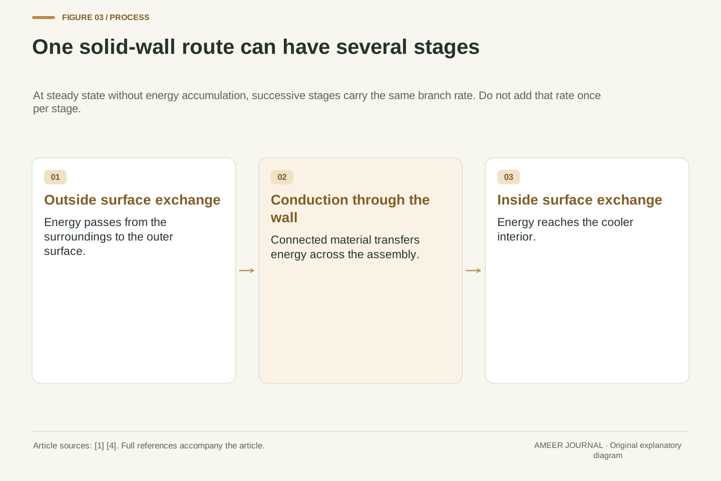
Follow one imagined route from the room to the interior. Energy passes from the room air to the outside of a wall, through the wall material, and then from the inside surface toward the contents. Convection and conduction can appear along that sequence [1][4]. If the route is carrying a steady 2 watts, those successive stages are not three separate 2-watt gains. They describe the same energy passing along a route, provided it is not accumulating in the wall during the interval.
Now draw a second route through the lid and a third through a support. Those can be separate branches across the boundary. A total budget can add the contributions of distinct branches when each contribution is defined consistently. This difference between stages and branches is the most useful detail in the box sketch. Colouring every mechanism differently can make a diagram attractive, but it can also tempt you to add quantities that should not be added. Label the complete path, its endpoints and the amount crossing your chosen boundary before calculating a total.
A steady series path may include an exterior convective resistance, conduction through several materials and an interior convective resistance. Under the idealized no-accumulation assumption, the energy rate through successive elements of that path is the same. Temperature drops divide across the elements; the full room-to-interior temperature difference is not independently applied across every layer [4]. Adding the heat rate at each interface would double-count or triple-count one physical transfer.
Parallel branches are different. A wall assembly, a separate lid assembly and a structural support can each provide a complete route between the external and internal regions. Their consistently defined contributions may be summed in the control-volume energy balance. The series-versus-parallel distinction is a modelling interpretation of the cited transfer mechanisms and assembly-resistance guidance [1][4]. It is not a new experimental result. A real design may need coupled temperature nodes, radiation view relationships and time-dependent storage; the elementary network is useful only when its assumptions and boundary locations remain visible.
Calculate the whole-box improvement
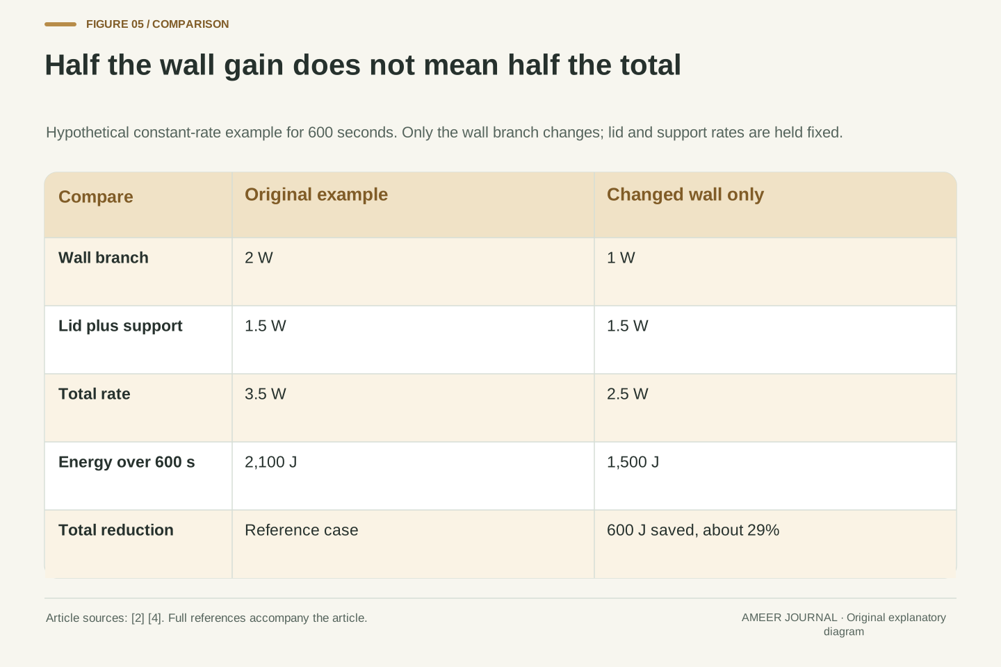
Here is a fully hypothetical short-interval budget. Assume the wall assembly admits 2 watts, the lid assembly 1 watt and a separate support 0.5 watt. Each number covers one complete branch across the same boundary. The total is 3.5 watts. If these assumed rates stay constant for 10 minutes, multiply by 600 seconds: the contents gain 2,100 joules. This is arithmetic applied to invented teaching values, not a reported test or a prediction for an actual box.
Now suppose a change halves only the wall branch, from 2 watts to 1 watt. Keep the other assumed branches unchanged. The new total is 2.5 watts and the 10-minute gain is 1,500 joules. The reduction is 600 joules, or about 29 percent of the original total. Halving the wall contribution did not halve the whole-box gain. You can check the result another way: the wall's 1-watt saving is only part of the original 3.5-watt total. Improving an already small branch would produce a smaller total change under the same assumptions.
Assign three hypothetical independent branch rates: P_wall = 2 W, P_lid = 1 W and P_support = 0.5 W. Their total is P_total = 3.5 W. Assume these values remain constant over Δt = 600 s, with all contributions defined at the same control-volume boundary and no omitted source. Then Q = P_totalΔt = 2,100 J. The numerical values are invented solely to illustrate energy accounting; no conductivity, dimension or temperature-dependent coefficient has been measured or inferred for a product.
Reduce P_wall by 50 percent while fixing P_lid and P_support. The revised total is 1 + 1 + 0.5 = 2.5 W, producing 1,500 J over the same interval. The relative total reduction is (3.5 − 2.5)/3.5 = 2/7, approximately 28.6 percent. This sensitivity calculation shows why a component improvement must be weighted by its share of the original total. Extending the result to a long cooling history would require updated temperatures and branch rates; converting the saved energy into a temperature difference would additionally require an appropriate model of the contents.
Compare conditions before comparing labels
A useful comparison starts with the same question and matching conditions. Were the two containers the same size? Did they start with the same contents at the same temperature? Were their lids opened equally often? Were they in the same surroundings? These questions identify changes that could alter the transfer paths or the energy stored inside. A result from one arrangement cannot automatically describe another. The building-science sources make a similar distinction between a material rating and the performance of its installed assembly [4][5].
Also check what was actually reported. A wall resistance, a heat-transfer rate and a time-to-temperature are different results. They need different supporting information. A resistance label needs its units and the assembly it covers; a heat-transfer rate needs its boundary conditions; a temperature history needs the contents and starting state. You can perform this evidence check by reading a specification or drawing a diagram. There is no need to heat objects, dismantle a container or use touch as a substitute for a controlled measurement. If an essential condition is missing, keep the conclusion correspondingly limited.
A fair comparison specifies geometry, area, initial conditions, contents, surrounding air and radiative conditions, and any exchange of matter through openings. The relevant evidence might be a material property, an assembly-level coefficient or a complete transient measurement. These are different levels of description. Building America explicitly distinguishes combined assembly resistance from nominal material resistance and identifies installation-related departures from assumed ratings [4]. DOE likewise emphasizes the interaction between insulation and other boundary components [5].
Units are part of that description: area-normalized thermal resistance is not the same quantity as the total thermal resistance of one complete branch. A quoted value without its unit system or area convention cannot be compared reliably with another value. Likewise, a measured interior-temperature curve cannot uniquely reveal every branch rate without additional information about thermal storage and boundary conditions. These limitations do not make measurements useless; they establish what a measurement can support. The reader's task is to match a claim to the quantity and conditions actually documented, rather than treating a single attractive number as a universal property.
Use the route map to ask better questions
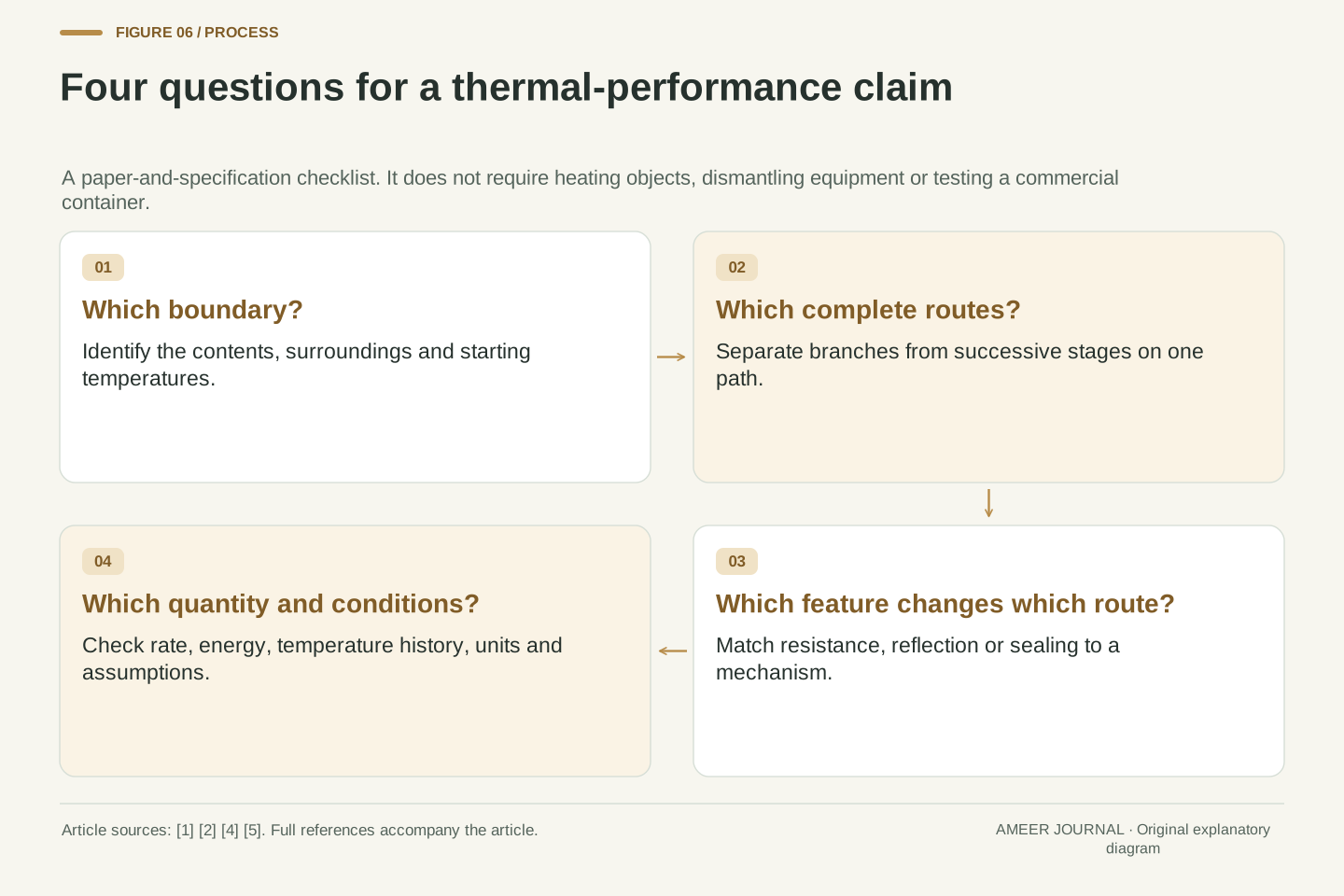
When you meet an insulation claim, first identify what is meant to stay warmer or cooler, and relative to which surroundings. Next trace the complete routes across its boundary. Ask which mechanism a proposed feature changes and whether another route remains open. The conduction, convection and radiation distinctions from NOAA, NASA and DOE help make these questions precise [1][3][5]. A thick layer, a quiet air space and a reflective surface should each have an identified role in the explanation.
Finally, inspect the comparison. Was a change reported for one component or for the whole system? Were the other conditions held fixed? Does the reported quantity describe a rate, an amount of energy or a temperature history? In our hypothetical calculation, a 50 percent reduction in one wall branch produced about a 29 percent reduction in the total heat gain. The difference came from the remaining routes, not from a mathematical trick. Keep the sketch and the energy budget together, and an insulation description becomes a set of claims you can examine rather than a promise you must accept on the strength of one label.
An efficient review of a thermal-performance claim proceeds from boundary definition to path identification, mechanism assignment and evidence matching. Establish the relevant temperature differences and distinguish solid bridges, fluid-mediated transport and radiative exchange. Specify whether resistances lie in series within a route or whether complete routes lie in parallel across the control-volume boundary [1][3][4]. An intervention should then be associated with a documented change in a particular physical quantity under stated conditions.
Use conservation of energy to check the resulting budget. Do not add successive interface transfers as independent gains, omit a bypass because it occupies little visible area, or convert a component percentage into a whole-system percentage without weighting its contribution. The hypothetical 2 W wall, 1 W lid and 0.5 W support example shows the calculation with every assumption exposed. Its value is the transferable reasoning procedure. A real performance prediction still requires suitable geometry, properties, boundary conditions and observations; neither a mechanism diagram nor this numerical example supplies those missing measurements.
Sources & further reading
Explore the references behind this guide. External pages may change after our review.
- The Transfer of Heat Energy | National Oceanic and Atmospheric AdministrationNOAA / National Weather Service · Accessed 6 Nov 2026
- Heat TransferNASA / Glenn Research Center · Accessed 6 Nov 2026
- NASA's Cosmicopia -- Ask Us - Space Physics - Heat, Temperature, and the Electromagnetic SpectrumNASA / Goddard Space Flight Center · Accessed 6 Nov 2026
- Building Science Introduction - Heat Flow | Building America Solution CenterPacific Northwest National Laboratory / Building America Solution Center · Accessed 6 Nov 2026
- Types of Insulation | Building Science EducationUS Department of Energy / Building Science Education · Accessed 6 Nov 2026
Article updated 6 Nov 2026.
Found something we should revisit?
Good explanations get better with thoughtful feedback.