What you’ll take away
- A gyroscope measures angular rate; zero rate after a turn does not restore the starting orientation.
- Fixed-axis angle change is the signed rate integrated over elapsed time and added to a starting angle.
- Actual interval durations matter; the same listed rates can give a wrong angle when their time weights are wrong.
- A constant rate bias accumulates into an angle error, and correcting offset does not establish sensitivity or axis alignment.
- General three-dimensional orientation requires consistent rotation composition, not three independent body-axis angle sums.
A zero reading can follow a perfectly real turn
Imagine a device that turns to face a new direction and then stops turning. Its ideal gyroscope reading returns to zero. Has the sensor forgotten the turn? No: a gyroscope measures how quickly the device is turning now, not a permanent record of where it is pointing. The accumulated angle belongs to a calculation that follows the rate over time. A zero current rate means that the angle is no longer changing about the measured axis; it does not force the angle back to its starting value. Manufacturer and platform documentation identify angular rate as the gyroscope's measured quantity. [1][2]
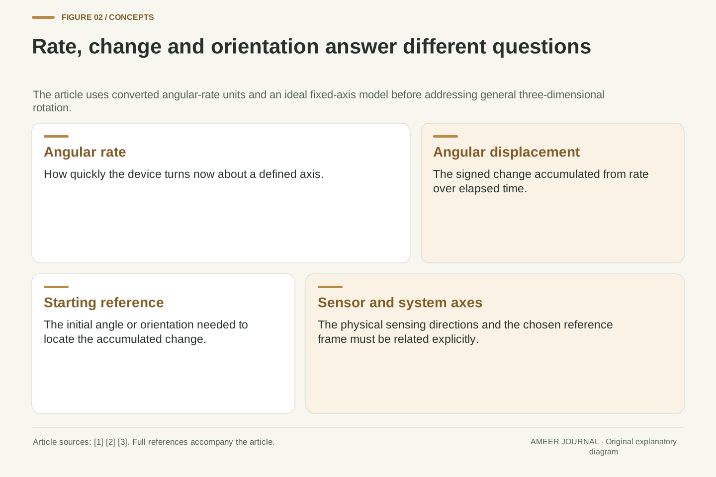
We will follow an imaginary device through a forward turn, a pause and a reverse turn. All numbers are constructed examples, not readings collected from a phone. Most calculations use one fixed turning axis and an ideal non-rotating reference frame, leaving reference-frame motion and other axes outside that model. We will add timing and calibration errors separately so their effects remain visible. The distinction is useful whenever a screen shows a rate, an angle or an orientation: those displays may be related, but they do not contain the same information. Reading the correct one is the first step toward explaining what a movement record means.
A rate gyroscope reports angular velocity components. Its ideal zero output after a completed turn is consistent with a changed orientation because instantaneous rate and integrated angular displacement are different quantities. Analog Devices describes angular-rate sensing and integration, while Android specifies gyroscope channels in radians per second and shows incremental rotation updates. [1][2] A rate channel is therefore not an absolute heading channel, even if software later uses it to maintain an orientation estimate.
The original scalar examples assume rotation about one fixed, correctly identified axis relative to a reference treated as non-rotating. The reported values are angular rates after conversion into physical units, not raw voltages or register counts. All intervals, initial angles and errors are stipulated. We first assume an ideal sensor, then introduce timing mistakes, constant additive bias and a separate scale factor. General three-dimensional motion is addressed with an explicit rotation-order example rather than silently applying scalar angle addition to body-frame rates. No gyroscope, application, motion platform or hardware accuracy test was run for this article.
The sensor responds to turning, not to a stored compass direction
A tiny electronic gyroscope need not contain the spinning wheel that the word may bring to mind. In the vibrating-mass design described by Analog Devices, a small structure repeatedly moves back and forth. When the device rotates, the Coriolis effect produces a response across that driven motion. The structure's movement changes capacitance, an electrical property that the surrounding circuit can detect. Within the described sensing arrangement, the resulting signal is related to angular rate. [1] This is a physical mechanism for observing a turn as it happens.
The important boundary is between that rate observation and the later angle calculation. A device that has finished turning can retain its new direction without continuing to generate the same turning-rate signal. Likewise, a device turning at a steady rate can keep reporting a steady nonzero number while its direction changes continuously. Neither behavior is contradictory. The hardware mechanism does not, by itself, supply a label such as “started at ten degrees” or “now faces north.” Those labels require a reference or an initial condition. Our numerical examples will keep that reference visible instead of hiding it inside a display.
The historical ADXRS explanation describes a driven resonating mass, a transverse Coriolis response and capacitive sensing of the resulting displacement. Its stated simplified response connects angular rate with the measured differential capacitance. [1] We use that mechanism to identify the measured variable, not to import the article's historical product specifications, performance claims or application guarantees. A rate-sensitive mechanical response does not mechanically retain the integral of every previous rate sample as an absolute directional reference.
For a single ideal axis, write the converted output as ω(t), the signed angular rate in the chosen frame. A constant nonzero ω describes ongoing rotation; ω=0 describes no current rotation about that axis. A stored angle estimate θ is a separate state updated from that signal and a starting value. Distinguishing measurement from state is essential when interpreting reset behavior: resetting a software angle to zero chooses a new numerical origin, whereas a zero rate observation only contributes zero change during the corresponding interval. The two zeros refer to different quantities and are not interchangeable evidence about physical orientation.
Attach a direction and a time unit to the rate
A value of 30 degrees per second means that a steady turn would add 30 degrees in one second about the named axis. A value of −30 degrees per second means a turn in the opposite signed direction. The sign depends on the documented axis convention, not on which way an observer happens to stand. Android uses a right-handed convention: viewed from the positive end of an axis toward the origin, a positive rotation appears counterclockwise. [2] Changing viewpoint without keeping that convention can reverse an explanation even when the data are unchanged.
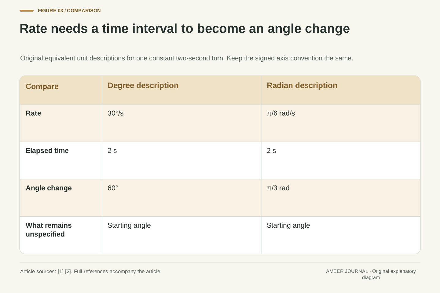
Some interfaces report radians per second instead of degrees per second. One full turn is 360 degrees or 2π radians. Thus 30 degrees per second equals π/6 radians per second, about 0.524 rad/s. Over two seconds, either description gives a 60-degree turn. Read the actual unit before doing arithmetic. Also identify the sensor's physical axis: a channel called z follows a device-defined direction, which is not automatically vertical in the room. Manufacturer guidance explains how sensing-axis alignment and mounting affect the relationship to a system's reference axes. [1][3]
For the stated positive-axis convention, ω=30°/s corresponds to π/6 rad/s. Multiplying by Δt=2 s gives Δθ=60°=π/3 rad. Android documents rad/s for its three gyroscope channels and gives a positive rotation convention referenced to the positive axis endpoint. [2] A numerical integral is meaningful only when rate and time units are compatible. Multiplying radians per second by seconds yields radians; a missing degree conversion changes the interpreted angle by a constant factor.
Axis identity is equally important. The sensor channels are components in the device coordinate system, while an application may require a room or system frame. A rigid mounting transformation and any residual axis misalignment affect that mapping. The alignment article distinguishes sensing axes from system reference axes and describes scale and cross-axis consequences. [3] Our scalar model aligns its single sensing axis with the fixed physical turning axis. It therefore avoids treating a changing body-axis direction as a permanent room direction. The right-handed sign convention, physical axis and frame assumption stay attached to every signed rate in the following tables.
Follow a forward turn, a pause and a reverse turn
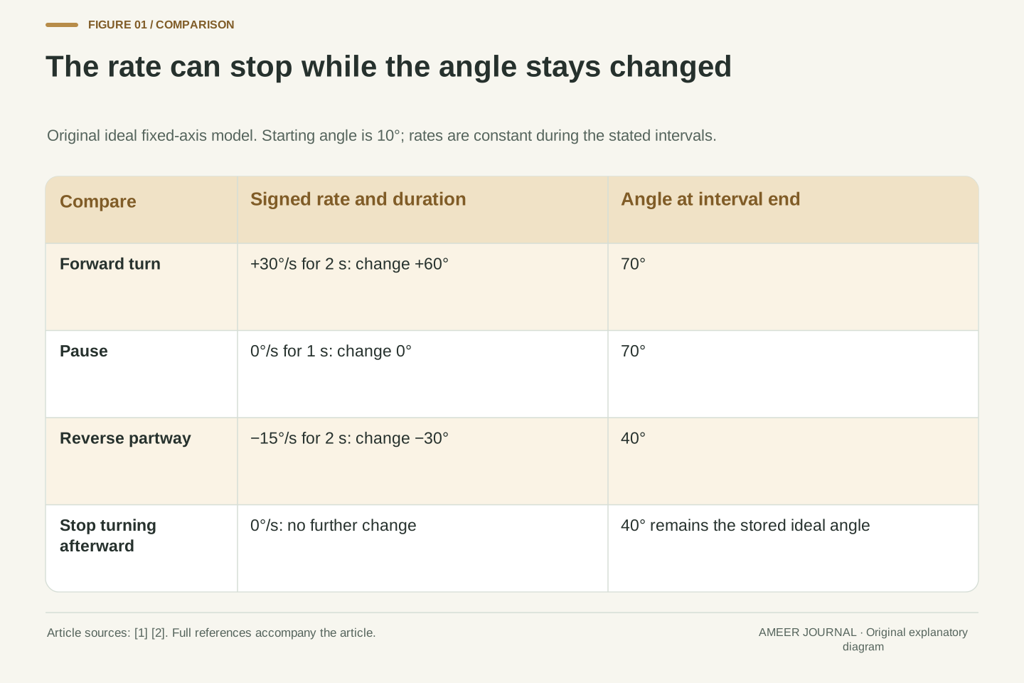
Set the starting angle to 10 degrees. First, let the device turn at +30 degrees per second for two seconds. The angle change is +60 degrees, so it reaches 70 degrees. Next, let it stop turning for one second. The rate is zero and the change during that second is zero, leaving the angle at 70 degrees. Finally, let it turn at −15 degrees per second for two seconds. That adds −30 degrees and leaves it at 40 degrees. If it then stops, the rate returns to zero while the angle remains 40 degrees.
The pause did not erase the first turn. The reverse turn undid only part of it. To calculate each interval, multiply its signed rate by its duration, then add the result to the previous angle. This is a simple form of integration, the rate-to-angle relationship described in the sources. [1][2] Our rates are constant within each stated interval, so these products are exact for the example. A real changing signal requires an appropriate integration method and timing information; the three clean intervals make the meaning of the calculation visible before those complications are introduced.
For fixed-axis rotation, θ(t)=θ0+∫ω(t)dt. With piecewise constant rate, the integral is exactly ΣωkΔtk. Set θ0=10°, then use the interval pairs (30°/s,2 s), (0°/s,1 s), and (−15°/s,2 s). Their signed increments are +60°, 0° and −30°, giving successive angles 70°, 70° and 40°. The net displacement is +30°. Zero rate after the final interval preserves the final integrated angle rather than restoring θ0.
The integral relationship is the bridge between the manufacturer's angular-rate description and the platform's incremental rotation example. [1][2] Here it is exact because the axis is fixed and the specified rates are constant within each interval. No approximation to an unknown motion is claimed. A real sampled signal requires a convention for the rate between timestamps, an initial state and an error account. If the software resets its integration state during the pause, a displayed angle may jump even while the gyro rate remains zero; that would be a state-management action, not evidence that the physical device rotated back.
The same changes can begin from different directions
Repeat exactly the same three intervals, but start at 200 degrees instead of 10. The changes are still +60, zero and −30 degrees, so the new final angle is 230 degrees. The gyroscope rate sequence is the same in both cases. It supplies the changes, not the missing starting direction. To express an angle relative to a chosen external reference, the calculation needs a starting value established in that reference. A label such as “heading” should therefore prompt a question about where that initial or continuing reference comes from.
There is another useful distinction in our first journey. The device turns through 60 degrees one way and 30 degrees back. Its net signed change is 30 degrees, but its total amount of turning along this one-axis path is 90 degrees. Adding the magnitudes answers a different question from adding the signed changes. A zero final rate answers neither question by itself. A single number at the end of the record cannot reconstruct the earlier journey. The time history, the starting reference and the definition of the requested angle are what make the result interpretable.
Changing θ0 from 10° to 200° while keeping the complete rate history fixed shifts every integrated angle by 190°. The final result changes from 40° to 230°, but the net displacement remains 30°. Thus integration of ideal fixed-axis rate determines angular displacement relative to an initial condition; it does not identify that initial condition from the same rate record. This is an original consequence of the integral, not a claim about a specific orientation estimator's initialization method.
For this path, signed displacement is ∫ωdt=60°−30°=30°, while total angular travel is ∫|ω|dt=90°. These are distinct statistics of the same ideal record. A displayed orientation may additionally wrap angles modulo a full turn, so an unwrapped accumulated angle and a wrapped directional display need not show the same number after repeated revolutions. Neither convention changes the measured instantaneous rate. Specify whether a result represents net displacement, total travel or orientation relative to a reference; otherwise, a correct calculation can appear inconsistent merely because its label hides which quantity was requested.
Unequal time gaps need unequal weights
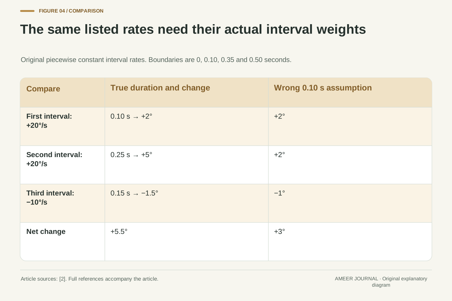
Now use a different original record with three intervals. For 0.10 second the rate is +20 degrees per second. For the next 0.25 second it remains +20. For the last 0.15 second it is −10. The angle changes are +2, +5 and −1.5 degrees, giving a net +5.5 degrees. If someone mistakenly assigns 0.10 second to every interval, the same listed rates produce +2, +2 and −1 degree, or only +3 degrees. The rate values did not change; their time weights did.
Our interval boundaries are 0, 0.10, 0.35 and 0.50 second. Their differences give the durations used above. Android's example forms a time difference from sensor-event timestamps before calculating an incremental rotation. [2] That is why a requested update rate is not a substitute for understanding the actual timing in a record. Here each rate is explicitly constant over its interval. For isolated real samples, a gap does not reveal the motion that happened between them. Any interpolation or held-value assumption needs to remain part of the explanation, especially when gaps or dropped data are present.
The second model uses boundary timestamps [0,0.10,0.35,0.50] s and piecewise constant interval rates [20,20,−10]°/s. Exact increments are [2,5,−1.5]°, totaling 5.5°. Replacing the true intervals [.10,.25,.15] s with [.10,.10,.10] s gives the incorrect total 3°. Simply adding the rate values yields 30°/s, which is still a rate-dimensional sum and is not an angle. The timing information is a necessary part of the integral.
Android's example computes an event timestamp difference, converts nanoseconds to seconds and uses that duration to form the incremental rotation. [2] We rely on the semantic need for elapsed time, not on a claim that the example code is an optimized or universally accurate estimator. Our constructed values are interval-held rates, so rectangular integration is exact by construction. Actual point samples do not determine all intervening motion; numerical quadrature depends on assumptions about that motion. Preserve timestamp meaning, clock units and missing-data policy rather than treating every delivered callback as proof of one identical physical interval.
A small rate offset becomes a growing angle error
Let the true device be still about our chosen axis, but suppose the converted rate reading contains a constant extra +0.2 degrees per second. Integrate that reading for 60 seconds and the angle estimate gains 12 degrees even though the true angle has not changed. After 300 seconds, it gains 60 degrees. The error is small when described as a rate and large when accumulated for long enough. Sensor documentation identifies bias and noise as issues that must be considered when rate is used to maintain an angle estimate. [2][3]
Collecting more samples during the same minute does not remove this particular constant offset. Each shorter interval adds a smaller error, but the intervals still add up to 60 seconds, so the total remains 0.2×60=12 degrees. A stable-looking rate is not automatically a correct rate. Real errors can also vary with time, temperature and noise; the manufacturer warns that a constant-bias assumption has limits. [3] Our calculation deliberately keeps the offset constant to isolate one mechanism. It is not a specification for any phone, nor a prediction that every real error grows in exactly the same way.
Use the scalar measurement model m(t)=ω(t)+b with constant b=0.2°/s. If the initial angle is correct and the integrator uses m without correction, the angle error is eθ(T)=∫b dt=bT. It equals 12° at 60 s and 60° at 300 s. For the stationary toy case ω=0, the whole accumulated change is error. If the initial angle already has error e0, the total becomes e0+bT: an initial-reference error persists as an additive offset while this rate bias contributes further error over time. Those two sources should not be merged into one unexplained drift label. Bias and noise are acknowledged in both the platform guidance and the manufacturer's calibration discussion. [2][3]
Partitioning the same duration into more intervals does not change this deterministic bias contribution: ΣbΔtk=bΣΔtk=bT. A higher sample count can affect other aspects of numerical reconstruction, but it does not cancel a constant additive term. Do not substitute a stochastic noise growth law for this calculation; no noise distribution, spectral density or bias-instability specification has been assumed. The manufacturer explicitly cautions that bias can vary between observations with time and temperature. [3] The example therefore demonstrates one controlled error mechanism while leaving the actual sensor's time-varying error model to separately established evidence.
A zero-rate correction needs a trustworthy zero-rate condition
Suppose an independently known stationary condition produces the three illustrative rate values 0.18, 0.22 and 0.20 degrees per second. Their mean is 0.20. These values have small invented deviations around an offset of 0.20; the deviations happen to cancel in this example. Treating the mean as the bias and subtracting it therefore removes that stipulated offset. Three values do not generally guarantee an exact real calibration. A later true rate of 40 degrees per second would be reported as 40.20 before correction and 40 afterward. These are made-up calibration numbers chosen to show the arithmetic, not measurements or a recommended sampling procedure for a particular sensor.
The known-still condition is doing important work. A steady reading of 0.20 could also represent a real slow turn from an ideal sensor. If software assumes that every steady reading must be bias, it can subtract a real motion signal. Even when the condition is valid, an imperfect correction leaves a remainder: subtracting 0.17 from a true offset of 0.20 leaves 0.03 degrees per second, which accumulates 1.8 degrees in a minute. Calibration information therefore needs its conditions and units. Manufacturer guidance emphasizes bias variation and the quality of the reference motion used in characterization. [3]
For the constructed known-rest observations [0.18,0.22,0.20]°/s, the arithmetic mean is 0.20°/s. Write these observations as b+ε with b=0.20 and ε=[−0.02,+0.02,0]°/s. Their chosen deviations sum to zero, so the sample mean equals the stipulated b exactly. This is a constructed cancellation, not a statistical guarantee that three real observations determine bias without uncertainty. If the estimate is instead bhat=0.17°/s, the residual b−bhat=0.03°/s integrates to 1.8° over 60 s. Establishing ω=0 independently is essential: the constant observation m=0.20 can also arise from ω=0.20 and b=0. A static-looking output alone does not identify which decomposition applies.
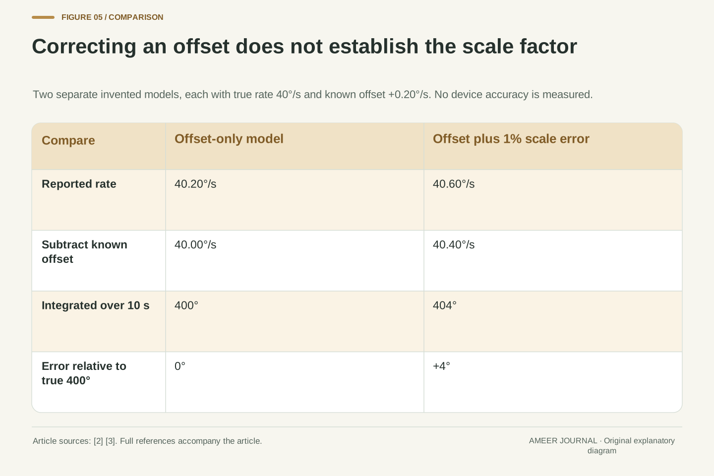
Offset is also different from sensitivity. In a separate model m=1.01ω+0.20, a true rate of 40°/s produces 40.60°/s. Subtracting the correct offset leaves 40.40°/s, still one percent high. Over a stipulated ten-second constant turn, the corrected integral is 404° rather than 400°, a 4° error. A zero-rate observation cannot determine that scale factor because its ω term vanishes. The alignment source discusses scale and cross-axis effects separately from residual bias and noise. [3] This example shows why one successful zero correction does not establish every aspect of angular accuracy.
Three rate channels are not three independent angle counters
Our earlier sums were deliberately limited to one fixed axis. For general three-dimensional turning, order matters. Picture an arrow initially pointing along a fixed upward z direction. A positive quarter-turn about fixed x moves it toward negative y; a following quarter-turn about fixed y leaves that direction unchanged. Reverse the order instead: the y turn moves the original arrow toward positive x, and the following x turn leaves it there. The two outcomes differ even though each sequence contains one quarter-turn about each of the same two fixed axes.
This geometric example explains why general orientation software keeps track of how rotations combine. Android's example turns a rate sample and elapsed time into a small rotation, then says to combine it with the current rotation. [2] The device's own axes can change their directions in the room during motion. Treating their three rate channels as three independent fixed-room angle counters would skip that relationship. An orientation output may use a rotation matrix or a quaternion to represent the combined result. Those are ways to describe a rotation; their presence does not eliminate timing, reference or sensor-error requirements.
Scalar fixed-axis integration does not generalize to three independent Euler-angle sums for arbitrary body-frame angular rates. A concrete rotation-order check uses active right-handed rotations about fixed world axes. Starting with ez=(0,0,1), Rx(90°) sends it to (0,−1,0), and Ry(90°) leaves that vector unchanged. In the opposite order, Ry(90°) sends ez to (1,0,0), which Rx(90°) leaves unchanged. Thus RyRx ez differs from RxRy ez. This is a geometric world-axis example, not an instruction to relabel body-frame gyro channels as world-axis commands.
Android's illustration forms an axis-angle increment from rate magnitude and elapsed time, converts it to a quaternion and a matrix, and calls for concatenation with the current rotation. Its separate rotation-vector sensor has orientation semantics rather than rad/s semantics. [2] The illustration supports the need to retain rotational state and composition order. An implementation must also choose and consistently apply frame, active/passive rotation and multiplication conventions. The example here does not prescribe one multiplication order for every library. It demonstrates why a correct one-axis sum cannot, by itself, validate an arbitrary three-dimensional orientation update.
Keep the rate record and the angle assumptions together
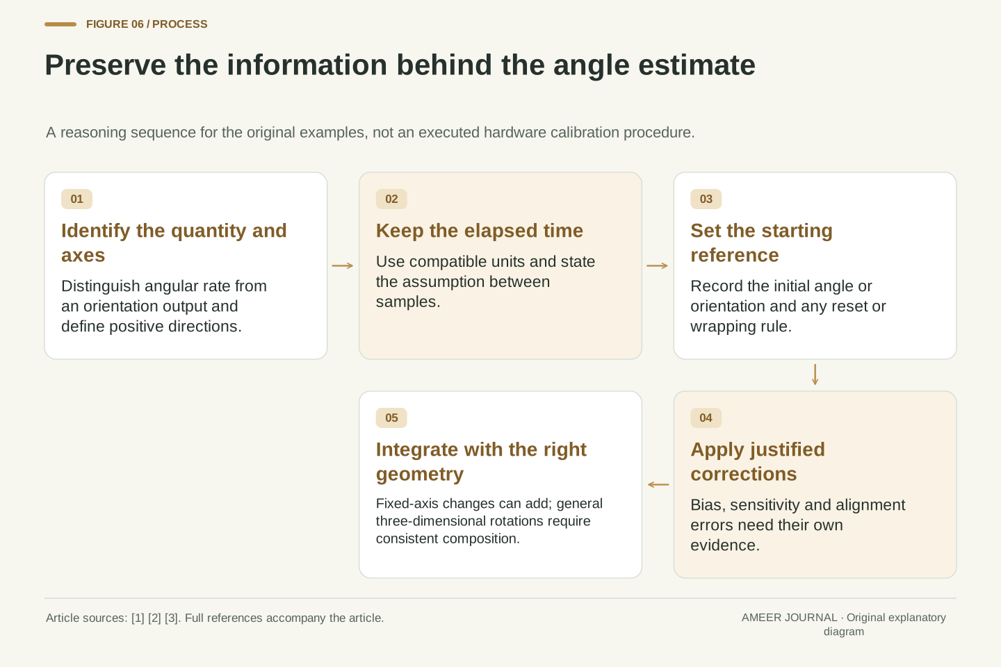
To explain a gyroscope result, keep the named axes, rate units and timestamps with the readings. For an angle estimate, also keep the starting reference, the integration method, any reset or wrapping rule and the corrections applied. Android distinguishes a gyroscope rate from a rotation-vector output, and its uncalibrated gyroscope still has some factory and temperature processing applied. [2] A label such as “raw” or “uncalibrated” therefore needs its documented meaning; it does not automatically describe every processing step that has or has not happened.
Our completed turn now has a clear explanation. Starting at 10 degrees, the +60-degree turn, pause and −30-degree turn finish at 40 degrees. Zero rate afterward means no further change about the chosen axis. It does not mean a return to ten degrees, a known compass heading or an error-free orientation estimate. Timing errors change the interval weights; bias accumulates with duration; scale and axis errors require their own treatment; and three-dimensional rotations need composition. A useful display can show a simple number, but a useful explanation keeps the assumptions that give that number its meaning.
A reproducible angle account retains rate quantity, axis mapping, units, timestamps, interval assumptions, initial orientation, integration convention, corrections and output wrapping. Android specifically distinguishes uncalibrated rate from drift-compensated rate while retaining factory and temperature compensation in the uncalibrated interface. [2] Do not infer processing state merely from an informal raw-data label. Likewise, a fused or derived orientation estimate is a different product from the underlying instantaneous rate stream, with its own reference and correction assumptions.
The numerical checks identify separate failure modes: the ideal path gives net 30° and total travel 90°; a changed initial angle shifts the final result without changing rates; unequal intervals give 5.5° rather than the incorrectly weighted 3°; constant bias gives 12° in 60 s; residual bias gives 1.8°; and the separate scale model gives 4° error over its stated turn. Each result follows from a declared original model. The central inference remains modest and useful: a rate of zero after a turn is compatible with a changed orientation, while maintaining an accurate orientation estimate requires more information and state than that final rate value alone.
Sources & further reading
Explore the references behind this guide. External pages may change after our review.
- New iMEMS® Angular-Rate-Sensing Gyroscope | Analog DevicesJohn Geen and David Krakauer / Analog Devices · Accessed 6 Nov 2026
- Motion sensors | Sensors and location | Android DevelopersAndroid Developers / Google · Accessed 6 Nov 2026
- The Basics of MEMS IMU/Gyroscope Alignment | Analog DevicesMark Looney / Analog Devices · Accessed 6 Nov 2026
Article updated 7 Nov 2026.
Found something we should revisit?
Good explanations get better with thoughtful feedback.