What you’ll take away
- Warning, departure correction and continuous centring are different functions, even when vehicle names overlap.
- A centre point inside a lane does not establish that the whole vehicle envelope is inside.
- Heading changes both the projected footprint and, under stated motion, the rate of sideways travel.
- An accurate-looking width or zero estimated centring error does not independently validate the estimated lane.
- Interpret current indications and operating conditions through the specific manual while retaining the required driver attention.
A steering correction answers a narrower question than you might think
A small steering nudge can feel like a message saying, “the car has everything lined up.” It establishes much less. A lane-support function may be trying to reduce an unintended departure near a marking. A different function may provide continuing assistance toward the lane centre. A warning may provide no steering assistance at all. The official descriptions distinguish these jobs, although names and combinations vary between vehicles. Feeling a correction therefore does not identify a complete control strategy, prove that the car is centred or establish that assistance will remain available. [1][2][4]
We can make the distinction clearer with a paper model. Picture a straight lane 3.6 metres wide and a rigid rectangle 4.4 metres long and 1.8 metres wide. Every numerical value below is invented for this explanation. The rectangle is a defined outline, not a claim about a real car, its mirrors or its tyres. We will follow its centre, its outermost edge and its direction separately. The examples are calculations, not instructions to drift toward a road marking or tests of a vehicle’s intervention threshold.
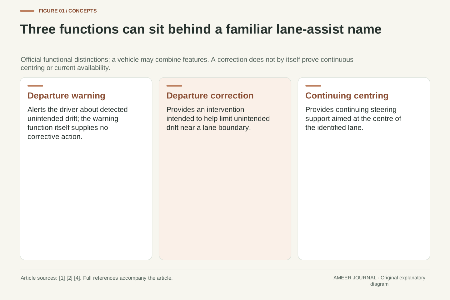
Lane departure warning, departure-oriented corrective assistance and continuous lane centring have different functional aims. NHTSA distinguishes a warning-only function from intervention intended to limit unintended departure and from continuously applied centring assistance. Transport Canada also notes that some systems described as lane keeping provide centring. These descriptions support a functional distinction, not a universal mapping from every manufacturer’s label to one controller architecture. One observed steering input cannot establish which objective, operating state or future action applies. [1][2][4]
The original geometry uses straight boundaries at lateral coordinates y=0 and y=3.6 m, with positive y to the right and forward direction x. A rigid rectangular envelope has length L=4.4 m and width W=1.8 m. Its centre offset e is measured from the true lane centre y=1.8 m; heading ψ is measured from the forward lane direction. These are stipulated quantities, not legal lane dimensions, sensor specifications or a vehicle model. The calculations expose distinctions among position, orientation, footprint and estimated reference. They do not model tyres, steering response or a production intervention threshold.
Separate a warning, a boundary correction and continuing centring
A lane departure warning asks whether the observed motion looks like an unintended departure and alerts the driver. In NHTSA’s description, that function supplies a warning rather than an action to avoid the crash. Lane keeping assistance adds a corrective action intended to help prevent unintended drift. Lane centring assistance provides continuing steering support aimed at the centre of the lane. That last word, “continuing,” is the useful distinction: a correction near an edge need not promise a sustained central path afterwards. [1]
A brochure may combine several of these functions under one familiar name. Transport Canada’s lane-keeping explanation explicitly includes systems that also help with centring, while its centring page describes continuous steering support. Read the behaviour described by the particular manual: what is monitored, when support operates and what the driver must still do. An occasional steering correction and continuous steering support can both be called assistance, but they answer different questions about the path. Neither description turns a single movement of the steering wheel into proof of the vehicle’s actual lateral position. [2][4]
For interpretation, separate three functions rather than assuming three mutually exclusive products. LDW provides a departure-related alert without a corrective action. LKA adds intervention intended to reduce unintended departure; NHTSA describes possible steering or wheel-based actions. LCA applies continuing steering inputs directed toward the lane centre. This taxonomy describes objectives and intervention patterns, not a shared actuator arrangement, guaranteed recovery path or standard response time across vehicles. [1]
There is a terminology overlap in the evidence: Transport Canada’s LKA page allows centring capability within some systems, whereas its LCA page contrasts continuing support with assistance activated near a line. Consequently, “has lane keeping” is an incomplete specification. The reader needs the stated objective, conditions for operation and current support state. A departure-oriented intervention could change heading without eliminating all centre offset. Conversely, a centring objective does not establish that the true boundary estimate is correct. Those are separate logical questions about what the feature aims to do and what its information can support. [2][4]
The centre can remain inside while part of the rectangle is outside
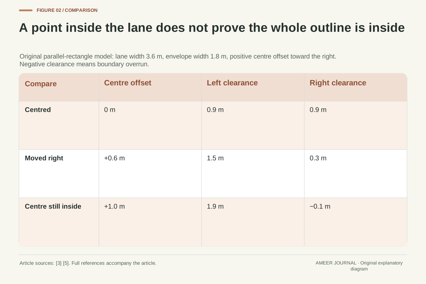
Start with the rectangle parallel to the lane. Its centre is halfway between the boundaries, at 1.8 metres, and half its width is 0.9 metres. That leaves 0.9 metres between each side and its corresponding line. Move the centre 0.6 metres to the right without turning the rectangle. The left margin becomes 1.5 metres, while the right margin falls to 0.3 metres. The lane has not narrowed and the rectangle has not widened: its position has redistributed the available space.
Now put the centre 1 metre to the right of the lane centre. The rectangle’s centre is at 2.8 metres, still between the lines at 0 and 3.6 metres. Its right side, however, reaches 3.7 metres. The right margin is −0.1 metre, meaning the outline extends 0.1 metre beyond the boundary. “The centre is inside” and “the whole outline is inside” are therefore different statements. A lane graphic that represents a position estimate cannot be interpreted without knowing which point, boundary and envelope the graphic represents. The real EX40 support page separately identifies sufficient lane width and visible markings as operating conditions. [3]
For ψ=0, the lateral half-span is W/2=0.9 m. With centre y_c=1.8 m+e, left and right signed clearances are c_L=y_c−0.9 m and c_R=3.6 m−y_c−0.9 m. Equivalently, c_L=0.9 m+e and c_R=0.9 m−e. At e=0 they are 0.9/0.9 m; at e=0.6 m they are 1.5/0.3 m. Their sum remains 1.8 m, the lane width minus the parallel envelope width. These are original geometric identities for the defined outline.
At e=1.0 m, y_c=2.8 m still lies inside the lane, but c_R=−0.1 m. A negative signed clearance denotes boundary overrun, not a negative physical distance between two separated surfaces. Whole-envelope containment requires both clearances to be nonnegative in this ideal representation; checking the centre alone is insufficient. Equality means contact with the mathematical boundary and supplies no positive margin. This is distinct from an actual feature’s activation rule. The retrieved EX40 manual conditions support on adequate lane width and detectable markings, but supplies no basis for identifying these invented clearances with its controller thresholds. [3]
Turning the rectangle changes the space it occupies across the lane
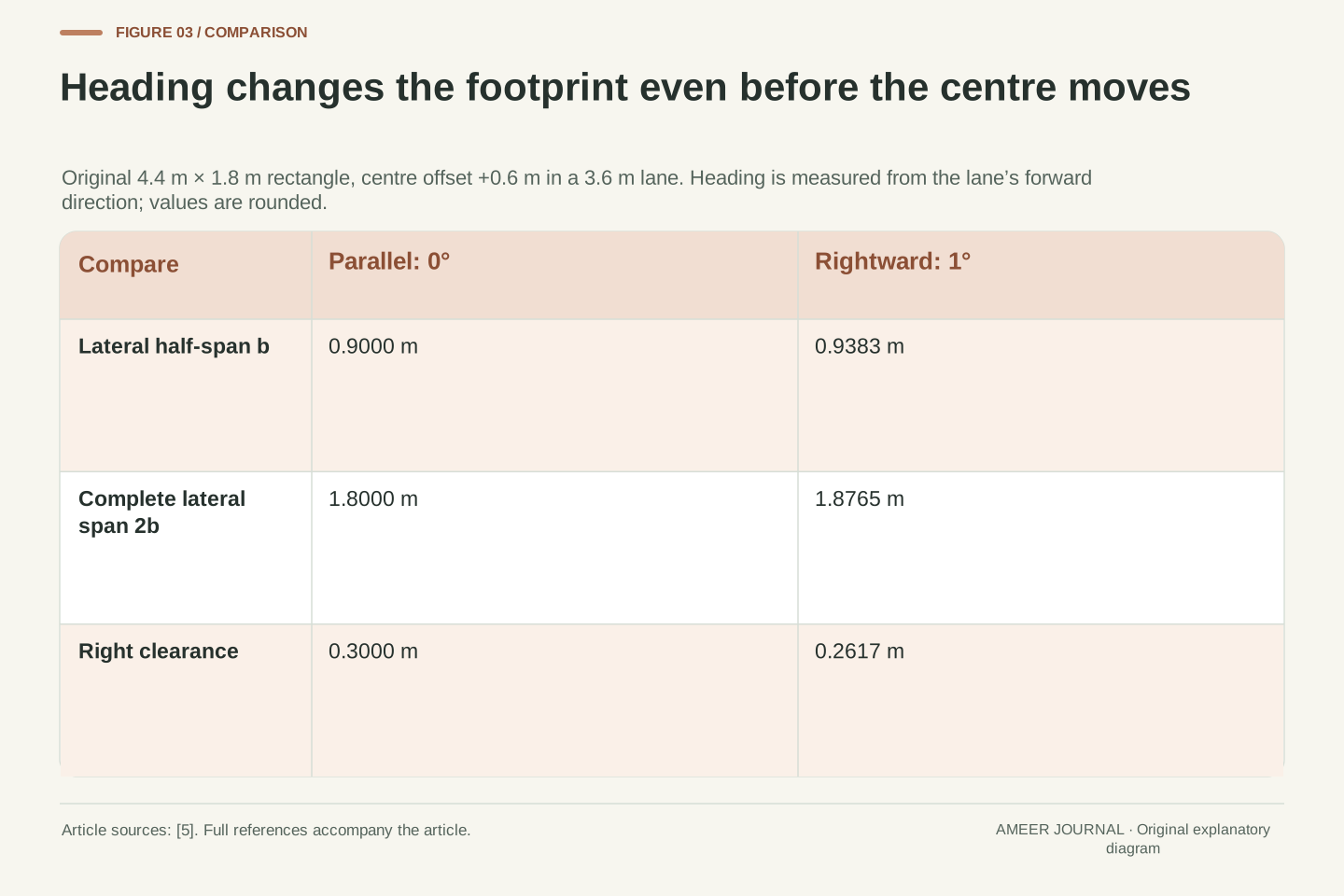
Position is only part of the picture. Keep the centre 0.6 metres to the right, then turn the rectangle by 1 degree toward the right. A little of its length now projects across the lane. The side-to-side width alone no longer describes the full sideways extent. Resolving the half-width and half-length into sideways parts gives a half-span of about 0.9383 metre, rather than 0.9 metre. This uses ordinary vector components: how much of a length points along each chosen direction. [5]
The right margin is now about 0.2617 metre. It was 0.3 metre when the same rectangle was parallel, so the change comes from orientation, not a sideways movement of the centre. A long object’s corners matter even at a small angle. This also explains why simply drawing a car icon between two lines can conceal an important assumption: the icon may not show the true shape or heading at a meaningful scale. Our rectangle has exact dimensions by definition. A real display’s icon is not an alternative way to measure body clearance, and no feature threshold follows from this sketch.
A rectangle’s lateral support extent follows by resolving its longitudinal and transverse half-axes. With ψ referenced to the lane’s forward x-axis, its lateral half-span is b=(L/2)|sin ψ|+(W/2)|cos ψ|. The absolute values select the maximum lateral extent over its corners. This is an original application of the component relationships and common-axis addition described by OpenStax; it is not an equation extracted from a vehicle controller. At ψ=0, it reduces to W/2 as required. [5]
For L=4.4 m, W=1.8 m and ψ=1°, b=2.2 sin(1°)+0.9 cos(1°), in metres, giving 0.9382582 m. At e=0.6 m, c_R=1.8 m−e−b=0.2617418 m. The complete lateral span is 2b=1.8765164 m; it is neither the width W nor the length L. Both position and orientation must therefore be specified before interpreting an envelope margin. The calculation assumes a fixed rigid rectangle and straight parallel boundaries. It includes corner projection but not body articulation, road curvature or an actual camera-to-body calibration.
A present margin and a future line crossing are different quantities
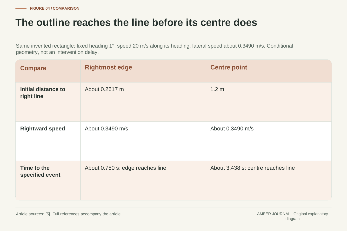
Now let that same 1-degree rectangle move at 20 metres per second along its own heading, without turning or changing speed. Its sideways speed is about 0.3490 metre per second. Divide the present right-edge margin, about 0.2617 metre, by that sideways speed. The outer edge reaches the line after about 0.750 second if the stated motion continues. This is a conditional paper calculation: none of the inputs describes a measured warning delay, steering response or time available for a real driver. The sideways component comes from the speed and its direction together. [5]
Using the centre point would produce a very different answer. The centre starts at 2.4 metres, leaving 1.2 metres to the right boundary. At the same sideways speed it would take about 3.438 seconds to reach that boundary. The outline reaches it first. That difference is not a disagreement between two clocks; they time two different events. Changing the heading would change both the sideways motion and the rectangle’s projected half-span. Our fixed-heading result therefore stops being the right calculation once that assumption changes, which is precisely why a frozen geometric sketch cannot predict an assistance system’s response.
For the separate constant-heading translation, velocity is aligned with the rectangle’s longitudinal axis and has magnitude v=20 m/s. Its lateral component is v_y=v sin ψ=0.3490481 m/s at ψ=1°. Because ψ is held fixed, b is constant, so the rightmost coordinate advances at the same lateral rate as the centre. With c_R=0.2617418 m initially, first right-boundary contact is t_edge=c_R/v_y=0.7498730 s. Components are resolved against the same lane axes used for the footprint. [5]
The centre-only time is (3.6 m−2.4 m)/v_y=3.4379213 s. It answers when a point reaches the boundary, not when the envelope first does. These formulas require a positive initial margin and rightward lateral velocity; zero or oppositely directed velocity changes the event logic. Heading variation would also make b time-dependent, while road curvature would change the boundary model. No steering dynamics, tyre-slip law, detection latency or driver reaction is supplied. The example consequently establishes a conditional geometric crossing time, not a real assistance trigger or a permissible delay before intervention.
Returning inward is not the same as settling on the centreline
Imagine two still pictures of the model. In one, the centre sits exactly in the middle but the rectangle points toward the right. In the other, it sits to the right but points parallel to the lane. The first has no centre offset at that instant, yet forward movement along its heading would create one. The second has an offset but, under the stated parallel motion, does not move farther sideways. Position and direction therefore describe different parts of the problem. A correct reading needs both, rather than treating a central-looking icon as a complete account of motion. [5]
A brief inward correction can address an approaching boundary without promising that the centre will settle exactly on the middle and stay there. Continuing centring has that different objective, as the official functional descriptions explain. This is about the stated aim, not a claim that every corrective system follows one particular path. The same steering sensation could occur with different starting offsets, headings and available information. From the sensation alone, a driver cannot work backward to a unique lane position or conclude that the feature will handle the next bend. [1][2][4]
At an instant, e=0 does not imply ψ=0 or a zero lateral rate. In the declared translation model, a centred rectangle with positive ψ has positive e_dot=v sin ψ. Conversely, e≠0 with ψ=0 can coexist with e_dot=0. These combinations show why lateral position and orientation are separate state quantities. They do not specify what steering command should follow: that would require dynamics, constraints and a defined objective absent from the paper model. [5]
NHTSA and Transport Canada distinguish departure-related corrective assistance from continuing centring, while acknowledging naming overlap. A successful reduction in outward motion is logically weaker than sustained tracking of a central reference. Nor does a nonzero steering input identify the position error that produced it; different states and operating conditions can lead to interventions. The useful reader question is therefore what behaviour the documented function aims to support, rather than whether any observed nudge proves a centred, stable future path. The evidence supports the functional distinction, not a universal feedback law, damping characteristic or control-gain recommendation. [1][2][4]
A perfectly followed estimate can still be displaced from the true lane
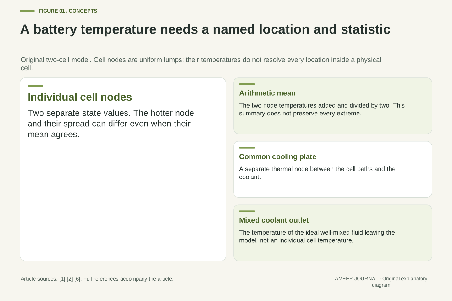
So far we have given the model the true boundaries. A support feature has to identify relevant markings from available information. The retrieved EX40 manual describes a forward-facing camera and lists ways road markings can be missed or misidentified. That creates another distinction: the line the system estimates and the physical boundary we mean may not be the same line. A smooth-looking response does not by itself check that reference. [3]
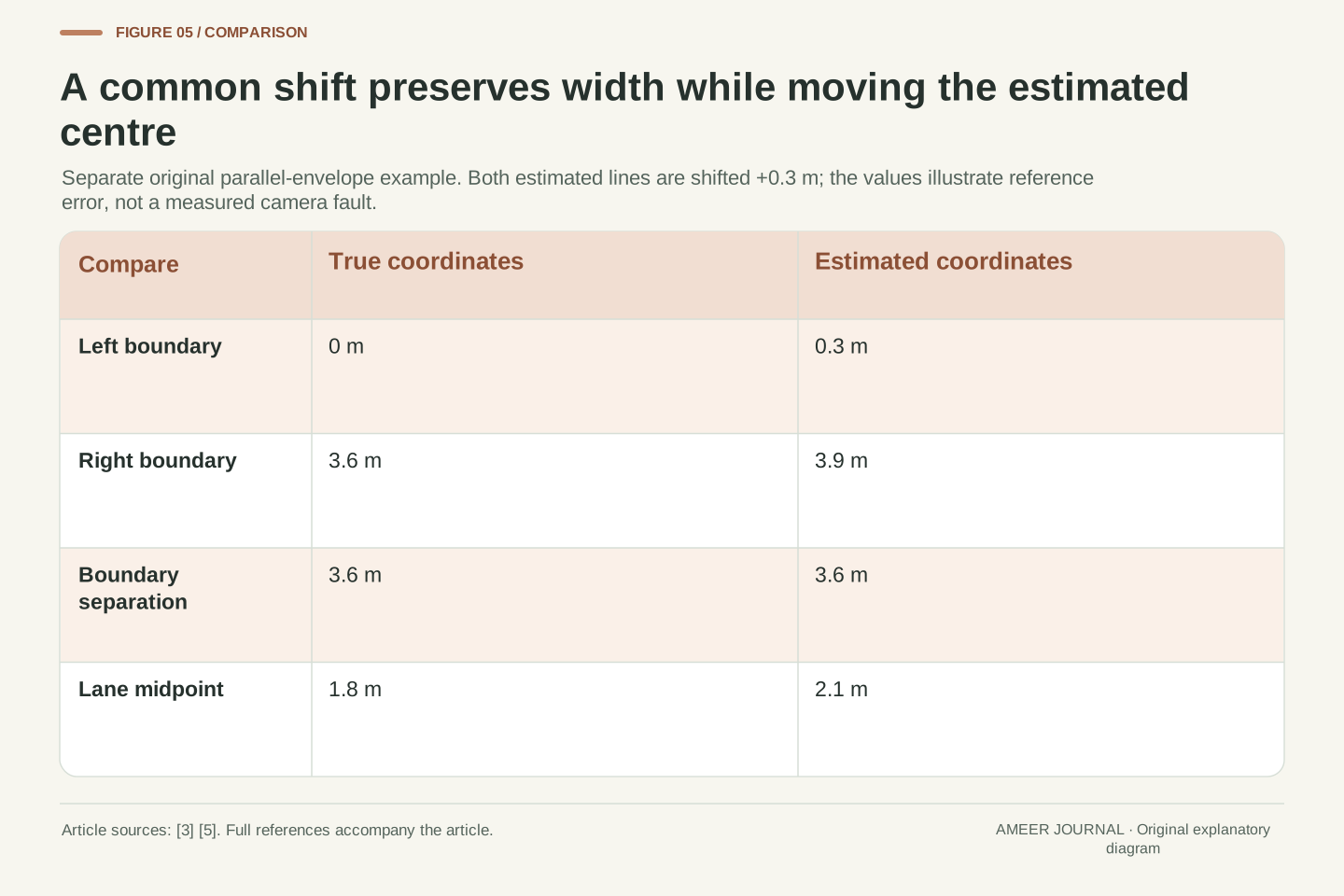
Return to a parallel rectangle and invent a simple error. The true lines remain at 0 and 3.6 metres, but the estimated lines are both shifted 0.3 metre to the right, to 0.3 and 3.9 metres. Their separation is still 3.6 metres, so a correct-looking width would not reveal this particular shift. The estimated centre is 2.1 metres instead of the true 1.8 metres. A rectangle exactly on that estimated centre has no estimated centring error, yet its true margins are 1.2 metres on the left and 0.6 metre on the right. The arithmetic illustrates a reference error; it does not describe a measured camera fault or suggest adjusting a real sensor.
Separate the true lane coordinates from a hypothetical estimated reference. In this parallel-envelope example, the true boundaries are y_L=0 and y_R=3.6 m. Shift both estimates by the invented common bias δ=+0.3 m: estimated boundaries become 0.3 and 3.9 m. The estimated width is unchanged because the common term cancels in the subtraction. The estimated midpoint, however, shifts by δ to 2.1 m. This is a coordinate argument, not a characterization of any particular estimator.
If the rectangle centre exactly tracks that estimated midpoint, its estimated error is zero while its true error is +0.3 m. With ψ=0 and W=1.8 m, actual margins are 1.2 and 0.6 m. Thus agreement with an internal reference does not validate that reference. The source basis is limited to the EX40 page’s camera-dependent marking identification and documented possibilities for misidentification. It provides no numerical bias distribution, calibration tolerance or recovery performance. Those are not inferred from the original shift example. [3]
A small positive estimate can hide a range that reaches beyond the line
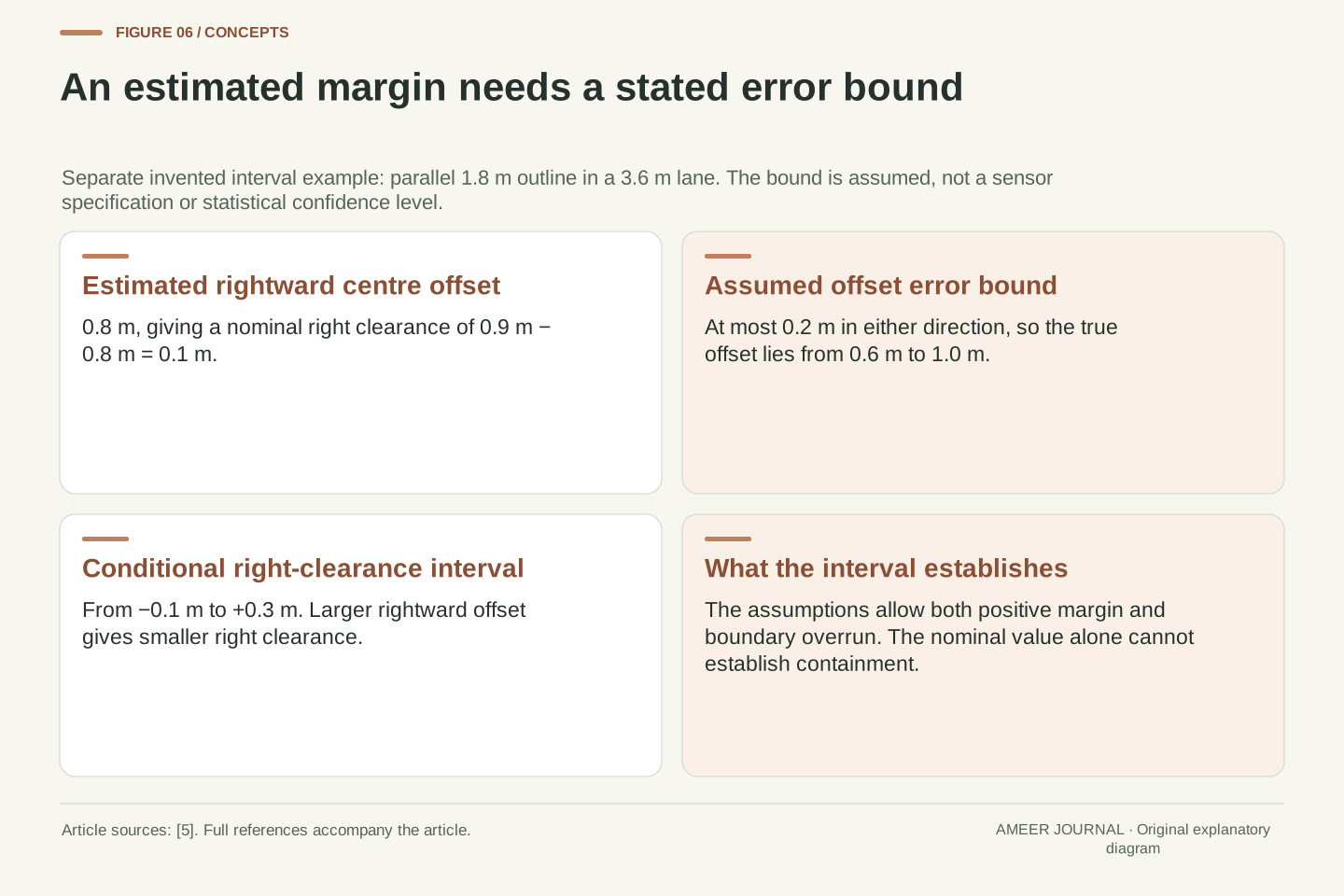
A number can also be uncertain without having the particular fixed shift just described. Keep the rectangle parallel and suppose its estimated centre offset is 0.8 metre rightward. The estimated right margin would be 0.1 metre. Now add a stated paper assumption: the true offset differs from that estimate by no more than 0.2 metre. The true offset could then lie anywhere from 0.6 to 1 metre. Subtracting those possible offsets from the available 0.9-metre half-margin gives right margins ranging from −0.1 to 0.3 metre.
That range includes both a positive margin and a small boundary overrun. The estimate alone cannot establish which applies. The assumed bound is not a measured error rate, a percentage confidence level or a specification for a real vehicle. It simply shows what information must accompany a claim about clearance. If the bound were absent, the calculation would not justify inventing one. If orientation were also uncertain, our parallel-only interval would leave out another changing part of the footprint. Keeping those assumptions visible makes the result useful without pretending that one reassuring number contains the whole situation.
For a separate stipulated interval example, let estimated offset e_hat=0.8 m and assume |e−e_hat|≤0.2 m, with ψ fixed at zero. Then e lies in [0.6,1.0] m. Since c_R=0.9 m−e decreases as e increases, the corresponding interval is c_R in [−0.1,0.3] m. The order reversal matters: the largest rightward offset produces the smallest right clearance. The nominal value 0.1 m is not a lower bound.
This is deterministic interval propagation under an assumed bound. It is not a statistical confidence statement, a normal-error model or a real sensor specification. It also holds heading and envelope dimensions exact; uncertainty in those quantities would require extending the calculation rather than reusing this result unchanged. The interval’s crossing of zero means strict containment cannot be established from these assumptions alone. No conclusion about a production warning threshold or risk probability follows. The purpose is to distinguish an estimate, an explicit uncertainty assumption and the conditional conclusion they jointly support.
The available marking evidence is part of the explanation
A camera sees visual evidence; it does not receive our paper model’s perfect coordinates. The EX40 page describes lane splits and merges that can cause temporary misidentification, and road works or diversions that can create conflicting sets of markings. It also identifies worn or distorted markings, road-repair edges, barriers and strong shadows as possible difficulties. These are documented limitations of that described feature, not a claim that every vehicle reacts identically to every such scene. [3]
There are two distinct problems here. Missing evidence may prevent the system from finding a lane at all. Ambiguous evidence may allow a line estimate that corresponds to the wrong visual feature. Our common-shift example explains why the second problem cannot be ruled out merely by a plausible width or apparently smooth tracking. Transport Canada’s centring page likewise connects performance to the ability to identify lane markings. These observations make the relevant manual’s conditions meaningful: they describe information the function depends on, not decorative small print around a guarantee of continuous control. [3][4]
The retrieved EX40 description ties its lane estimate to visible markings and a forward-facing camera. Its listed complications include splits and merges, conflicting road-work markings, deteriorated paint and misidentification of other edges or shadows. These support the existence of reference-selection and detection limitations, without quantifying their frequency or establishing a universal failure mode across different systems. No performance ranking is available from this documentation alone. [3]
Distinguish absence of an accepted lane estimate from acceptance of an incorrect reference. A plausible estimate width does not reject a common lateral shift, as the original coordinate example shows. Similarly, a continuous control response does not independently corroborate its own input reference. Transport Canada’s centring explanation requires identifying lane markings effectively and points to faded markings as a limitation. The combined evidence supports careful interpretation of availability and marking conditions, while leaving actual confidence thresholds, sensor fusion, road-edge handling and fallback behaviour to the specific implementation. [3][4]
Enabled, available and intervening are not interchangeable labels
A feature can be selected without being able to provide its usual assistance at that moment. The EX40 documentation explicitly distinguishes lane keeping that is active with visible markings from lane keeping enabled in settings but temporarily unavailable because markings cannot be detected. That is a useful example of why a saved preference and a current operating state should not be treated as the same fact. The page also describes driver-attention and active-steering conditions for that model. [3]
Do not turn those distinctions into universal dashboard colours or button instructions. The same page says certain safety steering interventions may occur even with lane keeping turned off in settings, so “off” does not support a blanket claim about every steering-related function either. Read the exact manual’s explanation of its indications and responsibilities. NHTSA’s descriptions of continuous steering assistance, or steering combined with acceleration and braking assistance, retain an engaged and attentive driver. Adding support in another direction does not make the lane estimate infallible or remove that responsibility. [1][3]
Separate configuration state, current operating availability and actual intervention. The EX40 page provides a concrete distinction between an active indication with detectable markings and an enabled-but-temporarily-unavailable indication when markings cannot be detected. It also states model-specific requirements concerning driver attention and active steering. These are documented semantics of that feature, not a standardized state machine shared by every manufacturer. [3]
The same source notes that some safety interventions can remain possible even when the lane-keeping setting is off. Therefore, a configuration bit cannot be generalized into proof that every lateral intervention path is disabled. Nor does combining longitudinal and lateral assistance establish unsupervised driving: NHTSA’s descriptions of continuous assistance in one or both control directions retain driver responsibility and attention. The practical interpretation rests on the exact function, conditions and indication, not on a single generic “on” label. No disabling, bypass, hands-off test or calibration procedure is needed to understand those distinctions. [1][3]
Read the reference and the conditions before trusting the impression
A useful description of lane assistance should make its job understandable. Is it warning about departure, providing a limited correction or offering continuing centring support? Then ask what establishes the lane reference, what operating conditions apply and what the current indication actually means. Those answers belong in the documentation for the particular vehicle. They are more informative than treating an impressive feature name or one gentle nudge as a complete account of what happened. [1][2][3][4]
The paper rectangle supplies a way to read such claims carefully. Its centre can be inside while an edge is outside. A small turn can change its sideways footprint. Its present margin and its future motion need separate information. An exactly followed estimate can still be shifted from the true lane, and a positive estimate can coexist with an uncertainty range that crosses the boundary. None of these deductions measures a real vehicle’s capability. Together they explain why assistance should be understood through its stated function and limits, with the attentive driving required by the official guidance. [1][3][5]
Interpret a capability statement by identifying the controlled objective, reference definition, operating conditions and present state. Departure correction and central tracking are different objectives; the estimated lane and the physical boundaries are different references; enabled and currently available are different states. The primary documentation supports those distinctions while leaving implementation-specific timing, sensing and intervention envelopes unspecified. [1][2][3][4]
The original calculations connect them without proposing a controller. Signed clearance requires a defined envelope; heading changes both projected extent and lateral motion; a fixed-heading crossing time is conditional on continued motion; common reference bias can survive an accurate width estimate; and a nominal margin does not replace an explicit error bound. These are separate claims with separate assumptions, so one reassuring display or steering sensation cannot establish them all. Use the particular manual to understand the assistance and the driver’s continuing role. The geometry explains why that reading matters, rather than supplying a road experiment, tuning recipe or verdict on a product. [1][3][5]
Sources & further reading
Explore the references behind this guide. External pages may change after our review.
- Driver Assistance Technologies | NHTSAU.S. National Highway Traffic Safety Administration · Accessed 7 Nov 2026
- Lane keeping assistanceTransport Canada · Accessed 7 Nov 2026
- EX40 Lane keeping aid | Volvo Support EN-CAVolvo Cars · Accessed 7 Nov 2026
- Lane centering assistanceTransport Canada · Accessed 7 Nov 2026
- 3.3 Vector Addition and Subtraction: Analytical Methods - College Physics 2e | OpenStaxOpenStax / Rice University · Accessed 7 Nov 2026
Article updated 7 Nov 2026.
Found something we should revisit?
Good explanations get better with thoughtful feedback.