What you’ll take away
- A three-port planetary gearset has two independent speeds; one fixed shaft speed does not fix both others.
- Fixed tooth counts constrain carrier-relative rotation without requiring a fixed engine-to-road operating ratio.
- Torque proportions and power fractions differ because each shaft has its own speed.
- A stationary reaction can carry torque at zero shaft power; reversed rotation can accompany positive input power.
- Machine-speed limits constrain the permitted combinations, while electrical and vehicle performance need wider system accounts.
Fixed teeth do not always fix the engine-to-road ratio
A fixed tooth count does not always fix the engine-to-road speed ratio. That familiar rule fits a two-shaft gear path, but a simple planetary unit has three accessible shafts. If all three can move, one shaft’s speed leaves a choice for the other two. This is the mechanism behind one kind of power-split arrangement: the gears stay engaged while the engine’s speed can change relative to the road-connected shaft. [1][2]
Toyota described a planetary power-split transmission in its March 25, 1997 announcement, with one branch connected to the wheels and electric motor and another to a generator. Adjusting the connected components’ speeds produced an electronically controlled continuously variable relationship. That dated description is an architectural example. Hybrids also use other arrangements, including series and parallel paths, so the explanation does not apply to every hybrid transmission. [3][4]
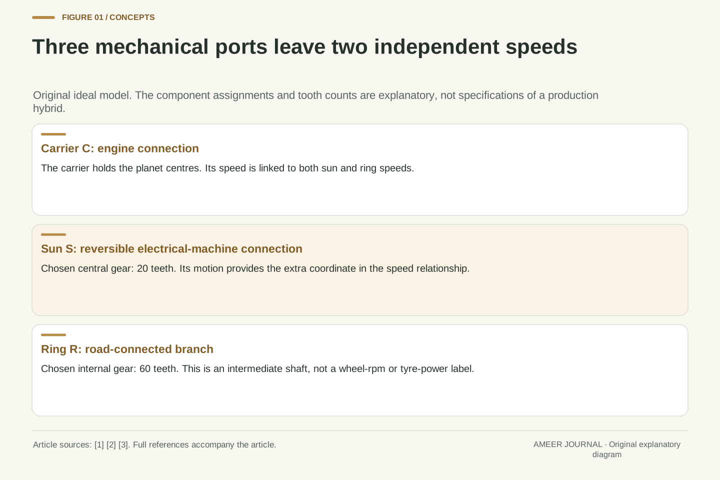
We will follow an invented, ideal gearset through several steady operating points. The model has no gear losses, changing stored energy or slipping teeth. Its engine connects to the carrier, a reversible electrical machine to the sun, and a road-connected branch to the ring. Those assignments and every number below define our example, not a particular Toyota specification or a vehicle test. They let us separate three questions: what can turn, what torque acts, and where power goes.
A three-port planetary constraint differs from a fixed two-shaft ratio. The sun, ring and carrier angular velocities satisfy one independent linear relation, leaving two independent shaft speeds. Consequently, holding the road-connected member at a specified speed does not uniquely determine the engine-connected member’s speed. A second controlled member can accommodate a different engine operating point without altering the tooth counts. [1][2]
Toyota’s March 25, 1997 announcement describes a planetary power-split device with wheel/motor and generator branches and an electronically controlled continuously variable transmission. This establishes the historical architectural use, not the member assignments or specifications of our calculation. DOE’s separate series and parallel descriptions also prevent treating one planetary model as a universal hybrid layout. [3][4]
Define an original simple rigid gearset with engine port C at the carrier, reversible electric-machine port S at the sun, and road-connected port R at the ring. All shaft directions use one common positive axis. Each numerical record is steady and lossless, with no change of rotational stored energy. We examine the gearset boundary alone; downstream gearing, electrical conversion and road loads require additional models. No production controller, vehicle measurement or software simulation supplies these values.
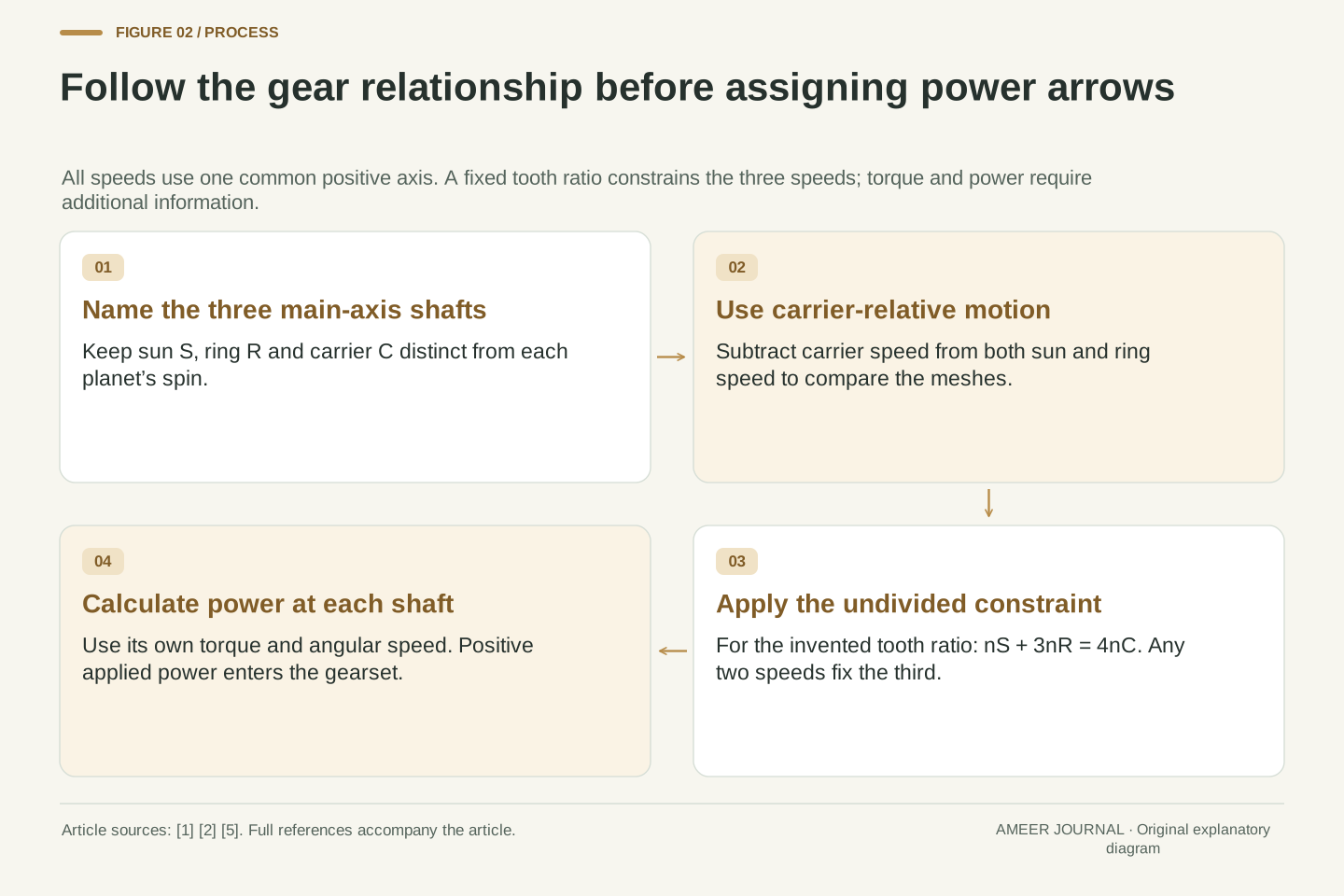
Name the sun, ring and carrier before following a power path
The sun is the central gear. The ring surrounds it and has teeth facing inward. Between them, planet gears mesh with both. Their centres are carried around the main axis by a separate member called the carrier. A planet can turn on its own pin while that pin travels with the carrier. The three accessible connections are therefore the sun shaft, ring shaft and carrier shaft; the carrier is not simply another name for a planet. [1][2]
Choose twenty teeth on the sun, twenty on each planet and sixty on the ring. With the same tooth-size system, the simple geometry requires the ring count to equal the sun count plus twice the planet count: 60 = 20 + 2 × 20. The ring-to-sun tooth ratio is three. These numbers establish the explanatory geometry; they do not specify bearings, strength, clearances or a complete gearbox design. [2]
Our ring connection leads toward the road through an unchanged downstream ratio. We will quote ring-shaft rpm, not wheel rpm. Holding that shaft steady corresponds to steady road speed only with the same downstream gearing and rolling conditions. The branch may also connect to an electrical machine in a wider hybrid arrangement. Its power at the gearset boundary therefore should not automatically be labelled power delivered at the tyres. [3]
A simple planetary unit contains an external sun, internal ring and intervening planet gears whose centres are located by a carrier. The planets both spin and orbit. Ports S, R and C refer to the main-axis sun, ring and carrier shafts, rather than treating a planet’s spin as an additional accessible driveline port. These distinctions matter because the carrier supplies the moving reference frame used to relate the meshes. [1][2]
Let N_S = 20, N_P = 20 and N_R = 60. For the stated common-module geometry, pitch radii are proportional to tooth count and N_R = N_S + 2N_P. Hence g = N_R/N_S = 3. The selected counts satisfy that geometrical identity; planet spacing, detailed tooth profiles, load sharing and durability are not being designed. The torque and speed calculations use the ideal simple-gear constraint only. [2]
Port R is an intermediate road-connected shaft. With a fixed downstream ratio and unchanged rolling conditions, its fixed angular velocity corresponds to fixed road speed, but its numerical rpm is not wheel rpm. Any traction-machine contribution on that branch, final-drive loss or tyre work occurs outside the chosen boundary. Naming this port precisely prevents a valid internal power balance from becoming an unsupported claim about complete vehicle propulsion. [3][5]
Look from the carrier to see the fixed relationship
Imagine describing each rotation from a viewpoint travelling with the carrier. A sun speed is then measured relative to the carrier, and so is the ring speed. In that moving view, the planet centres stay in place and the mesh becomes easier to understand. The relative sun and ring rotations have opposite signs, with their ratio set by the tooth counts. This carrier-relative relationship is often called the Willis equation. [2]
For our three-to-one tooth ratio, the rule can be written without a division: sun rpm + 3 × ring rpm = 4 × carrier rpm. All three speeds use the same positive direction. A negative value means rotation opposite to that direction, not a fault or a negative number of turns. Rearranging gives sun rpm = 4 × carrier rpm − 3 × ring rpm. [1][2]
The carrier speed is also a weighted average: one quarter of the sun speed plus three quarters of the ring speed. The greater weight belongs to the larger ring tooth count. If all three members turn at 1,000 rpm, the equation still works. Their relative speeds are then both zero, so dividing one relative speed by the other would be unhelpful; the undivided equation avoids that zero-over-zero expression.
In the carrier frame, the sun and ring speeds are ω_S − ω_C and ω_R − ω_C. The external sun/planet mesh reverses relative rotation, while the internal planet/ring mesh preserves it. Eliminating the planet gives the Willis relation (ω_S − ω_C)/(ω_R − ω_C) = −N_R/N_S wherever the denominator is nonzero. The undivided form is N_S(ω_S − ω_C) + N_R(ω_R − ω_C) = 0. [2]
Substituting the chosen counts yields ω_S + 3ω_R = 4ω_C. The same linear equation holds for rpm because every term receives the same unit-conversion factor: n_S = 4n_C − 3n_R. This is the native kinematic expression also documented by MathWorks, with g = N_R/N_S. It is separate from any torque-transfer convention used elsewhere in that software documentation. [1][2]
Solving instead for the carrier gives n_C = n_S/4 + 3n_R/4. At n_S = n_R = n_C = 1,000 rpm, the linear relation remains valid although both carrier-relative speeds vanish. Using the divided Willis expression there would create 0/0, not demonstrate an impossible operating point. The weighted constraint is the appropriate representation for this equal-speed case and for the subsequent comparisons.
One ring speed permits several engine speeds
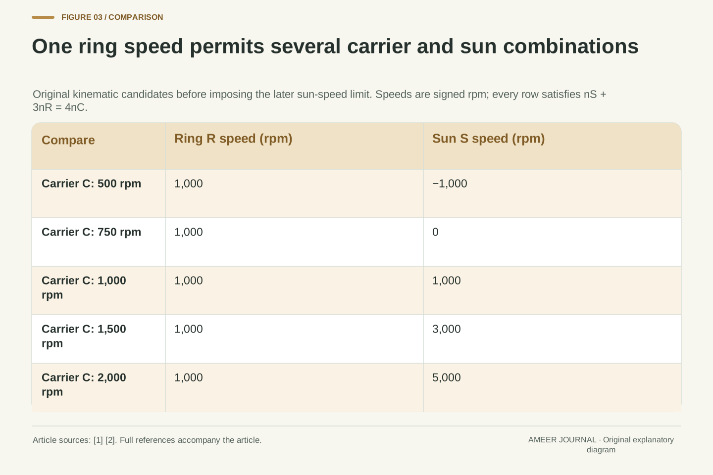
Hold the ring at an invented 1,000 rpm. If the carrier turns at 1,000 rpm, the equation requires the sun to turn at 1,000 rpm too. Raise the carrier’s stipulated speed to 1,500 rpm and the sun must turn at 3,000 rpm: four times 1,500, minus three times 1,000. The road-connected shaft has stayed at the same speed while the engine-connected carrier has changed. [1][2]
Other points on the same line are equally easy to calculate. A carrier speed of 2,000 rpm requires a sun speed of 5,000 rpm. A carrier speed of 750 rpm requires a stationary sun. At 500 carrier rpm, the sun must turn at −1,000 rpm, opposite to our positive direction. These are kinematic candidates before any machine limits are imposed; we will add one such limit later.
Check the 1,500-carrier case from the moving viewpoint. The sun is 1,500 rpm faster than the carrier, while the ring is 500 rpm slower. Their relative speeds have opposite signs and a magnitude ratio of three, exactly as the tooth counts require. The different engine speeds therefore need no change in tooth count and no slipping connection. They use the third moving member to satisfy the same fixed equation. [2]
Set n_R = 1,000 rpm, giving n_S = 4n_C − 3,000 rpm when n_C is expressed in rpm. At n_C = 1,000 rpm, n_S = 1,000 rpm. At n_C = 1,500 rpm, n_S = 3,000 rpm. Thus the same ring speed admits different carrier speeds when the sun is allowed to change accordingly. The equation constrains the triple, not a single constant carrier-to-ring ratio. [1][2]
The other constructed triples, in carrier/ring/sun order, are 2,000/1,000/5,000 rpm, 750/1,000/0 rpm and 500/1,000/−1,000 rpm. Each satisfies n_S + 3n_R − 4n_C = 0 exactly. A negative sun speed is permitted by this signed kinematic relation. Whether any triple is available to an actual machine requires additional speed, torque and control constraints; none is supplied by tooth count alone.
For the 1,500/1,000/3,000 case, n_S − n_C = +1,500 rpm and n_R − n_C = −500 rpm. Their ratio is −3, matching −N_R/N_S. This independently checks the relative-frame derivation. It also explains why subtracting the carrier matters: the absolute ratio 3,000/1,000 is positive, while the relevant carrier-relative ratio is negative. Mixing those two ratios would describe a different mechanism. [2]
Variable operation comes from a third connection
The gearset has two independent speed choices. Once any two shaft speeds are fixed, the third follows from the equation. Fixing only the ring leaves a whole line of carrier and sun combinations. This is more precise than saying the engine is completely independent of the wheels. It has room to change speed, but only while another connected member supplies the required motion. [1][2]
Holding a member still adds another condition. If the sun is fixed at zero, the carrier turns at three quarters of the ring speed. If the ring is fixed instead, the sun turns four times as fast as the carrier. Those are particular fixed-ratio cases of the same gearset. Letting the third member move removes that extra zero-speed condition; it does not make the gear teeth stretch or change size. [2]
In a power-split system, the electrical machine and controller help manage the connected operating points. Toyota’s historical description explains the continuously variable result through coordinated component speeds. But a possible speed pair is not automatically an efficient or available one. The mechanism explains how speed adjustment can occur; torque capability, electrical paths and control objectives still decide which point is usable. [3]
The constraint has rank one in three accessible shaft speeds, so it leaves two independent coordinates. Specifying n_R alone reduces the possibilities to a line in the n_C–n_S plane; specifying both n_R and n_C fixes n_S. It would be incorrect to command all three arbitrarily, or to call the carrier unconstrained simply because its ratio to the ring can vary. [1][2]
Setting n_S = 0 gives n_C/n_R = 3/4 for nonzero n_R. Setting n_R = 0 gives n_S/n_C = 4 for nonzero n_C. A held member supplies the additional condition that makes a two-port ratio apparent. With all members free to rotate, the tooth ratio remains three but no constant carrier/ring speed ratio is imposed. This distinction separates fixed geometry from a fixed overall operating ratio. [2]
The continuously variable relationship described in Toyota’s dated announcement is therefore compatible with permanently meshing gears. Coordinated shaft operation, rather than a changing tooth count, supplies the adjustment. Kinematic freedom nevertheless does not solve a controller’s optimization problem: torque availability, electrical power exchange and operating limits remain additional information. The following mechanical balance examines one admissible ideal torque set without assuming a production control strategy. [3]
A fixed torque proportion is not a fixed power percentage
For the ideal steady gearset, the external torques have a tooth-count relationship too. Choose an engine torque of +200 newton-metres applied to the carrier. The corresponding torques applied by the external branches are −50 newton-metres at the sun and −150 at the ring. They add to zero. The negative signs identify their directions on the gearset; the gearset applies the opposite torques back to those branches. [2]
The sun and ring torque magnitudes are one quarter and three quarters of the carrier torque. That does not mean one quarter of the engine’s power must always go to the sun. Power also depends on how fast the relevant shaft turns. In the earlier 1,500-carrier case, the sun turns twice as fast as the carrier, while the ring turns more slowly. Multiplying torque by each shaft’s own speed changes the power proportions. [5]
Use one sign rule throughout: a positive shaft-power value enters the gearset, and a negative value leaves it. A positive torque is measured in our common positive rotation direction. Torque sign alone cannot decide power direction, because shaft speed can also be negative. Keeping those two signs separate will become essential when the sun reverses later. [5]
For the stated ideal steady member balance, the physical externally applied torques satisfy T_S:T_R:T_C = N_S:N_R:−(N_S + N_R). Choosing T_C = +200 N·m therefore gives T_S = −50 N·m and T_R = −150 N·m. All torques use the same axis and are applied to the assembly; their sum is zero. This follows the university force/torque derivation, not an unspecified internal torque-transfer definition. [2]
The result can also be checked by ideal virtual power. Substitute ω_C = (ω_S + 3ω_R)/4 into T_Sω_S + T_Rω_R + T_Cω_C. The coefficients of the two independent velocities become T_S + T_C/4 and T_R + 3T_C/4. Both vanish for the chosen torques. Thus the torque vector is proportional to the constraint’s normal vector, and the net mechanical power is zero for every admitted steady velocity triple. [1][2][5]
The magnitudes |T_S|/T_C = 1/4 and |T_R|/T_C = 3/4 are torque ratios. Applied power is P_i = T_iω_i, with positive values entering the gearset and negative values leaving it. These power fractions also contain shaft-speed ratios, so a fixed ideal torque proportion does not establish a fixed power split. Reversing both a torque and its associated angular velocity makes their power product positive. [5]
Calculate each power at its own shaft speed
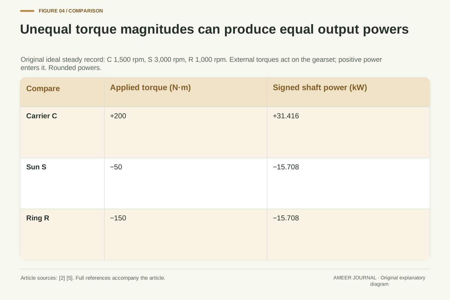
Return to carrier 1,500 rpm, sun 3,000 rpm and ring 1,000 rpm, with the +200, −50 and −150 newton-metre torques just defined. Converting rpm into radians per second and multiplying by torque gives about +31.416 kW at the carrier, −15.708 kW at the sun and −15.708 kW at the ring. The two equal outgoing powers add to the incoming power. Each branch receives half, despite their unequal torque magnitudes. [5]
Now put all three shafts at 1,000 rpm while retaining the same torques. Carrier input becomes about 20.944 kW, sun output about 5.236 kW and ring output about 15.708 kW. Here the outgoing power fractions really are one quarter and three quarters, because all three shafts share the same speed. This is a different operating point, with less engine-side power, not a different set of gear teeth.
The comparison shows what an unexplained power-split percentage leaves out. Tooth counts determine the ideal torque relationship, but power percentages need the speeds at the same operating point. A diagram that assigns one permanent fraction to the electrical branch would miss the first case. Nor can we turn the sun’s outgoing mechanical power directly into battery charging power; the electrical conversion and other electrical loads still have to be accounted for. [3][5]
Use ω = 2πn/60 with n in rpm and P = Tω. At n_C = 1,500 rpm, ω_C = 50π rad/s, so P_C = 10,000π W. At n_S = 3,000 rpm, P_S = −5,000π W. At n_R = 1,000 rpm, P_R = −5,000π W. Their exact sum is zero. The rounded values are +31.416, −15.708 and −15.708 kW, and both outgoing fractions are 1/2. [5]
At the separate all-members-1,000-rpm point, P_C = 20,000π/3 W, P_S = −5,000π/3 W and P_R = −5,000π W. These are approximately +20.944, −5.236 and −15.708 kW. The sun and ring output fractions become 1/4 and 3/4. The torques have not changed, but the carrier and sun angular velocities have, so their powers change while ring power stays fixed.
In general, for positive carrier input in this model, −P_S/P_C = n_S/(4n_C) and −P_R/P_C = 3n_R/(4n_C). Their sum is one through the kinematic constraint, but each fraction varies with the admitted speed pair. The fractions describe mechanical gear-port power only. They do not include machine conversion loss, electrical storage or the rest of the driveline, and cannot establish fuel consumption or battery charging. [1][3][5]
A stationary sun can carry torque without taking shaft power
Choose carrier 750 rpm and ring 1,000 rpm. The sun is now stationary, because 4 × 750 − 3 × 1,000 is zero. Keep the same ideal torques: +200 at the carrier, −50 at the sun and −150 newton-metres at the ring. The sun still supplies a reaction that helps satisfy the torque balance, even though its shaft makes no angular movement. [1][2]
Its mechanical power is therefore zero: a finite torque multiplied by zero speed gives zero. Carrier input and ring output are each about 15.708 kW in magnitude. All the gearset’s incoming mechanical power leaves through the ring in this particular steady record. The stationary member’s role has not disappeared; zero work rate and zero torque are different conditions. [5]
This is also why a stationary electrical-machine shaft does not prove that the wider system consumes no electricity or produces no heat. The simple calculation describes mechanical transfer at that shaft. It has not supplied an electrical loss model or any holding-current requirement. A real system’s electrical demand cannot be read from the zero-rpm label alone, just as the nonzero reaction torque cannot be called generated mechanical power.
At n_C = 750 rpm and n_R = 1,000 rpm, the constraint gives n_S = 0. With the same external torques, T_S remains −50 N·m while P_S = T_Sω_S = 0. Carrier power is 200 × 25π = 5,000π W, and ring power is −150 × 100π/3 = −5,000π W. The steady ideal gear-port balance closes without assigning power to the stationary reaction. [1][2][5]
The reaction remains mechanically relevant: removing T_S while leaving the other two external torques unchanged would no longer satisfy the assumed ideal torque set. Zero shaft speed eliminates work through that coordinate, not the moment it contributes. The carrier and ring continue rotating while the sun supplies the required nonmoving mechanical boundary in this constructed operating point.
This mechanical result does not evaluate the electrical machine at S. An actual holding-torque state may involve electrical loss, and the gearset account provides neither its current nor temperature behavior. MathWorks’ power bookkeeping explicitly distinguishes applied shaft power, dissipation and changing stored energy. Our steady lossless boundary sets the latter gear terms to zero; it does not assert that every connected component is lossless. [5]
A component called a generator can supply mechanical power
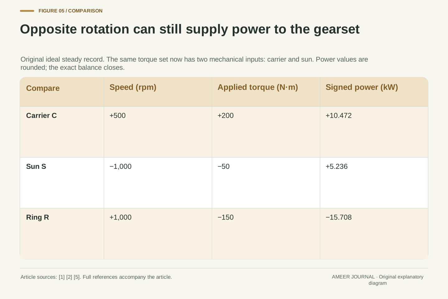
Lower the carrier’s stipulated speed to 500 rpm while the ring remains at 1,000 rpm. The sun must turn at −1,000 rpm. Its applied torque is still −50 newton-metres in our unchanged ideal torque set. Both numbers are negative, so their power product is positive: the sun branch now sends mechanical power into the gearset instead of receiving it. Rotation direction alone would not reveal that change. [1][2][5]
The carrier supplies about 10.472 kW and the sun supplies about 5.236 kW. Together they provide the ring’s outgoing 15.708 kW. Ring output is therefore one and a half times the carrier input, with the extra half supplied by the sun branch. Nothing has multiplied energy inside the gears. The full balance simply has two mechanical inputs at this operating point.
For a reversible electrical machine attached to the sun, supplying mechanical power toward the gearset is the motoring role, even if a simplified system picture calls that component a generator. The picture’s component name does not fix its instantaneous power direction. We still cannot identify the electrical energy source: another machine, a battery and conversion losses would need their own account before drawing a charging or discharging arrow. [3][5]
For n_C = 500 rpm and n_R = 1,000 rpm, n_S = −1,000 rpm. The sun’s external torque remains T_S = −50 N·m, so P_S = (−50)(−100π/3) = +5,000π/3 W. The positive value indicates input to the gearset despite negative rotation and negative applied torque. This sign product is essential; identifying generation from the speed sign alone gives the wrong answer. [1][2][5]
Carrier input is P_C = 200 × 50π/3 = 10,000π/3 W, while ring output is P_R = −5,000π W. Hence P_C + P_S + P_R = 0 exactly. The rounded inputs, 10.472 and 5.236 kW, sum to the 15.708 kW output. The output/carrier-input ratio is 3/2 because the sun provides an additional input equal to half the carrier contribution.
At the declared reversible machine port, positive mechanical delivery into the gearset corresponds to a motoring role. A persistent generator label is therefore inadequate as an operating-state description. The calculation does not establish battery discharge, however: the electrical network has not been specified. Its other machine exchanges, storage rate and conversion losses must be included before assigning an electrical source or sink. The three-shaft mechanical balance alone cannot resolve them. [3][5]
A machine-speed bound narrows the available choices
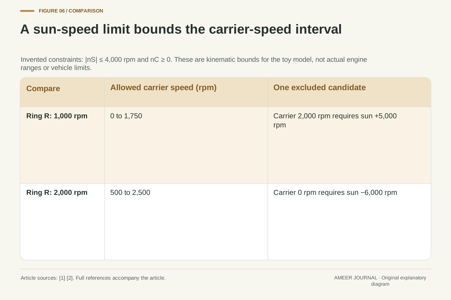
Add one invented constraint: allow the sun shaft no more than 4,000 rpm in either direction. Also restrict the carrier to nonnegative speeds. With the ring at 1,000 rpm, the sun-speed rule permits carrier speeds from zero to 1,750 rpm. Our earlier 1,500-carrier point fits, but the 2,000-carrier point would require 5,000 sun rpm and is excluded. The gear equation has not changed; the additional limit has narrowed its usable candidates. [1][2]
Now set the ring to a different steady speed of 2,000 rpm. Keeping the same invented sun limit gives a carrier interval of 500 to 2,500 rpm. A stationary carrier would require the sun to turn at −6,000 rpm, beyond that bound. Thus a limit on one machine can impose a lower as well as an upper bound on another shaft’s speed.
These intervals answer a kinematic question only. They are not real engine operating ranges or an electric-only speed threshold for a particular hybrid. A complete system could have additional couplings, different limits and control requirements. Even inside our interval, available torque, electrical power and thermal conditions would still need to support the chosen point. Freedom to vary speed is valuable, but it is bounded freedom.
Impose the hypothetical constraint |n_S| ≤ 4,000 rpm and n_C ≥ 0. At n_R = 1,000 rpm, −4,000 ≤ 4n_C − 3,000 ≤ 4,000, with all terms expressed in rpm. Solving gives −250 ≤ n_C ≤ 1,750 rpm; intersecting with nonnegative carrier speed leaves 0 to 1,750 rpm. The candidate n_C = 2,000 rpm requires n_S = 5,000 rpm and fails the imposed bound. [1][2]
At n_R = 2,000 rpm, the same calculation is −4,000 ≤ 4n_C − 6,000 ≤ 4,000, giving 500 ≤ n_C ≤ 2,500 rpm. A zero-speed carrier would require n_S = −6,000 rpm. This demonstrates how the offset in the three-port constraint converts a symmetric machine-speed limit into an asymmetric allowable carrier interval at a specified ring speed.
Only the stated speed constraints define these intervals. They do not include a combustion engine’s permitted running range, electrical-machine torque envelope, loss maps or a production controller’s mode changes. Nor do they establish an achieved vehicle speed or universal engine-off boundary. The algebra identifies candidates to be checked against a fuller model; satisfying the speed relation remains necessary within the toy architecture but insufficient for an available operating point.
Read a power-split diagram in three separate passes
First read the connections and speeds. Identify which member is the sun, ring and carrier, and which vehicle component connects to each. Check the tooth ratio and any held or disconnected member. Then ask whether a quoted rpm belongs to the engine, an electrical machine, an intermediate shaft or a wheel. The same diagram can be misread simply by treating all those speed labels as if they named one shaft. [1][2]
Next read torque and mechanical power together. A fixed torque proportion needs each shaft’s speed before it becomes a power fraction. A stationary reaction can carry torque without shaft work, and a reversed shaft can supply positive input power. These are connected consequences of the same calculation, not exceptions requiring the gears to create energy. A useful power diagram names the operating point and makes its arrows agree with the signed power balance. [5]
Finally, extend the boundary only when the missing information is available. Battery charging needs an electrical account; fuel use needs an engine account; tyre delivery needs the rest of the driveline. Toyota’s historical description itself includes control inputs and electrical-machine paths beyond the planetary device. The gearset explains why a hybrid can change engine speed at a steady road speed. It does not, on its own, decide how efficiently the complete car uses that possibility. [3][4][5]
Begin with topology and kinematics: name the S/R/C connections, signed speed convention, tooth-count ratio and active constraints. The governing relation n_S + 3n_R = 4n_C supplies two independent speeds, while held members and imposed limits reduce the allowed set. A variable effective carrier/ring ratio is compatible with fixed teeth because the sun provides another moving coordinate. [1][2]
Then establish the mechanical boundary. External torque directions, each shaft’s own angular velocity and P = Tω determine the power signs. The original examples show a 50/50 output split, a 25/75 split, a zero-power reaction and a two-input condition using the same ideal torque vector. Their differences arise from the admitted velocity triples. A fixed percentage without a specified quantity and operating point loses that information. [2][5]
Finally add the electrical and vehicle systems explicitly. Conversion losses, battery storage rate, other machine contributions and downstream mechanical losses are absent from the gear-only account. Toyota’s historical description names additional control factors and routes for generated electricity, while DOE describes alternative hybrid architectures. Those details determine how the kinematic opportunity is used. Separating them from the planetary constraint supports a precise mechanism explanation without inventing a fuel-economy result, battery state or production control law. [3][4][5]
Sources & further reading
Explore the references behind this guide. External pages may change after our review.
- Planetary Gear - Gear train with sun, planet, and ring gears - MATLABMathWorks · Accessed 7 Nov 2026
- 9.8 Planetary gears – Applied MechanicsJönköping University, Applied Mechanics · Accessed 7 Nov 2026
- Toyota Introduces New Passenger Vehicle Hybrid System | Toyota Motor Corporation Official Global WebsiteToyota Motor Corporation · Accessed 7 Nov 2026
- Alternative Fuels Data Center: Hybrid Electric VehiclesU.S. Department of Energy, Alternative Fuels Data Center · Accessed 7 Nov 2026
- Planetary Gear - Ideal planetary gear with sun, ring, and carrier - SimulinkMathWorks · Accessed 7 Nov 2026
Article updated 7 Nov 2026.
Found something we should revisit?
Good explanations get better with thoughtful feedback.