What you’ll take away
- Field-pattern speed, physical rotor speed and induced-current pattern speed describe different objects.
- Slip uses the field speed as its denominator; rotor electrical frequency also depends on pole pairs.
- A synchronous rotor can retain a constant angle behind a chosen excitation reference while matching its speed.
- The fraction 1 − slip describes a classical rotor conversion boundary, not the complete input-to-shaft efficiency.
- The same shaft rpm can fit different excitation records, so torque and efficiency need additional evidence.
Ask what is rotating before comparing speeds
Two motors can receive the same electrical frequency yet turn their shafts at different speeds. The missing information is how each rotor develops torque. In an induction motor, the rotating magnetic pattern must move relative to the conducting rotor to induce its working current. A synchronous motor uses a different relationship: during synchronous operation its rotor follows the excitation pattern at the same average speed. [1][2]
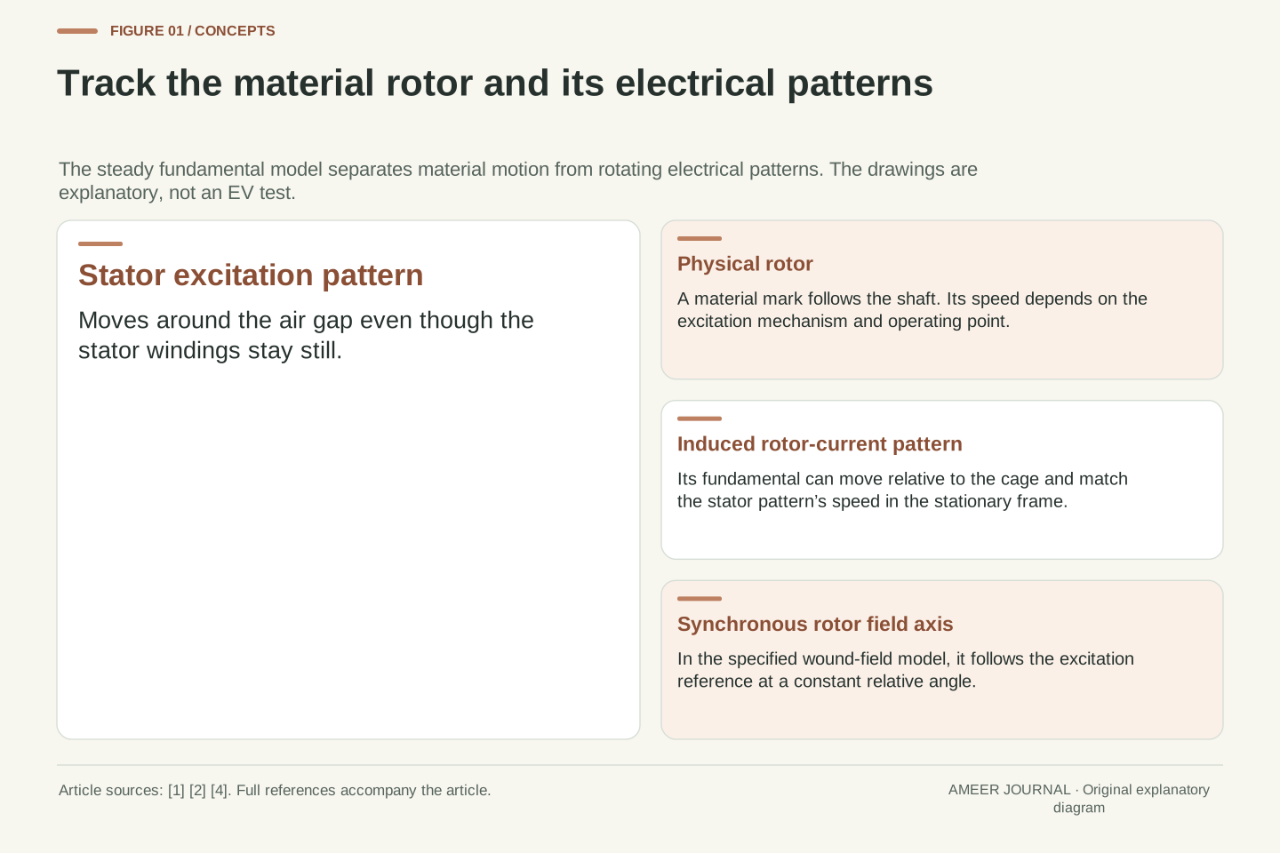
There are three things worth keeping separate: the metal rotor, the rotating stator excitation pattern, and the pattern formed by currents in an induction rotor. The stator is the stationary part around the rotor. Its magnetic pattern can rotate while its windings remain still. The rotor current pattern can also move relative to the metal carrying that current. Calling all three ‘motor speed’ hides the mechanism. [1][4]
The examples below are invented calculations for balanced, steady, forward motoring with one sinusoidal excitation pattern. They compare a cage induction model with a sinusoidal wound-field synchronous model. They are not specifications or tests of an EV. Keeping that scope explicit lets us answer a useful question precisely: when can a speed difference be necessary, and when can a fixed angle difference do the work?
A stator fundamental frequency and pole-pair count determine the speed of a rotating excitation wave, not by themselves the physical speed of every rotor architecture. The classical cage induction machine develops induced rotor current at a nonzero relative electrical frequency. In the balanced synchronous model, rotor excitation and the stator excitation reference instead maintain a constant electrical displacement while their mechanical angular velocities agree. [1][2]
This distinction requires named objects and frames. Let n_s denote the fundamental stator-wave mechanical speed, n_r the physical rotor speed, f the stator electrical fundamental in hertz, and p the number of pole pairs. The rotor-current spatial fundamental is a third object; it need not be fixed to a material mark on the rotor. A current wave moving through conductors is not a second physical shaft. [1]
All numerical records here are original hypothetical steady cases at positive frequency, with balanced sinusoidal excitation and harmonic effects omitted. The synchronous comparison uses the declared wound-field model in the MIT notes. No universal torque-angle law for permanent-magnet or salient machines is assumed. These restrictions make the frame and energy accounts closed enough to compare without implying a production vehicle architecture or a simulated result. [1][2][3]
A moving field does not require moving stator coils
A row of stationary coils can produce a magnetic pattern that moves around the motor. Their currents change at different times, so the strongest part of the combined pattern progresses around the air gap. Nidec explains the induction principle by separating the moving magnetic influence from the coils that create it. MIT describes the stator excitation as a rotating or travelling wave. The winding hardware itself does not have to follow that wave. [1][4]
The number of pole pairs tells us how many electrical pattern cycles fit into one complete mechanical revolution. Two pole pairs mean four poles, with the magnetic arrangement repeating twice around the circumference. With that arrangement, fifty electrical cycles each second correspond to twenty-five complete pattern revolutions each second. Multiply by sixty seconds per minute and the field-pattern speed is 1,500 rpm. [1][2]
Write this as field rpm = 60 × electrical hertz ÷ pole pairs. The chosen fifty hertz is the useful excitation frequency in this example, not a count of inverter switching pulses. Also check whether a document lists poles or pole pairs: four poles and two pole pairs describe the same arrangement, but substituting four into a formula expecting pairs would halve the calculated speed. [1][3][5]
Balanced phase-displaced currents in spatially distributed stator windings create a rotating fundamental. The conductor positions remain stationary while the field/current distribution changes in time. In the MIT representation, a pattern such as cos(pθ − ω_e t) has constant-phase locations satisfying pθ − ω_e t = constant. Differentiating gives its mechanical angular velocity Ω_s = ω_e/p. This is a statement about pattern propagation, not physical motion of stator copper. [1][2][4]
Since ω_e = 2πf, conversion from radians per second to revolutions per minute gives n_s = 60f/p. With f = 50 Hz and p = 2, Ω_s = 50π rad/s and n_s = 1,500 rpm. One full mechanical revolution passes two electrical cycles in this spatial arrangement; an electrical cycle therefore advances a chosen wave peak through half a mechanical turn. [1][2]
Notation deserves an explicit check. Throughout this article p counts pole pairs. Nidec’s characteristics page labels its own p as the total number of motor poles; that document’s symbol cannot simply be imported into the pair-based expression. The equivalent total-pole formula would use 120f divided by that count. The frequency here is the stator sinusoidal fundamental, not a PWM carrier or the physical shaft’s revolutions per second. [3][5]
Why the induction rotor needs relative motion
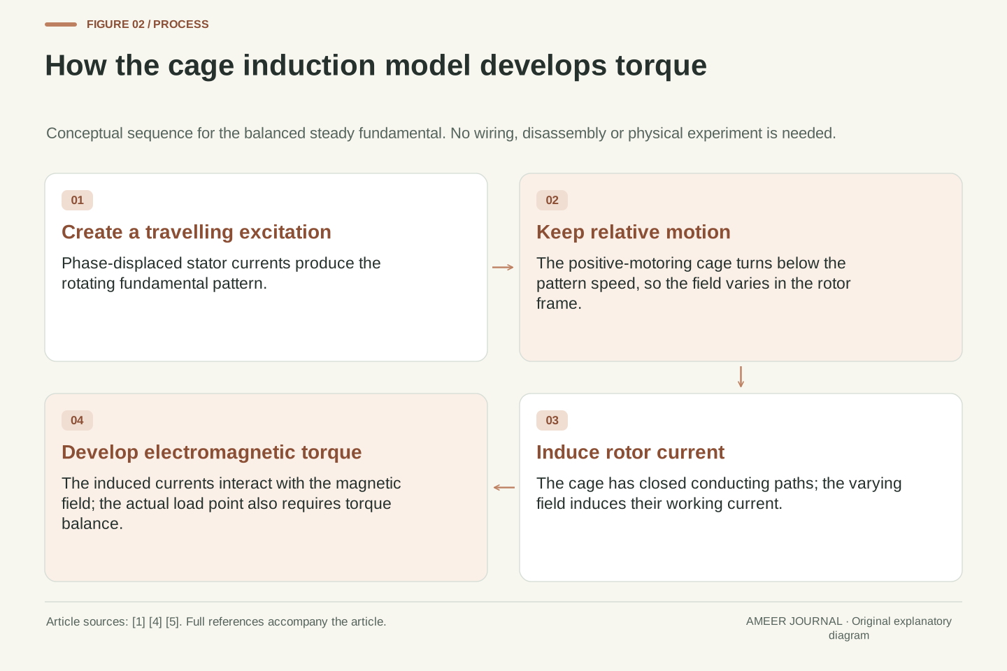
A cage rotor contains closed conducting paths. When the stator magnetic pattern moves past them, it induces electrical activity in those paths. The resulting currents interact with the magnetic field and produce torque. That sequence explains why a cage induction rotor can be driven without giving its rotor winding a separate working electrical supply in this model. The stator supplies the changing magnetic influence across the air gap. [1][4]
Now imagine that the metal exactly catches up with the steady fundamental pattern. From the rotor’s point of view, that pattern is no longer sweeping past. In the ideal cage model with finite rotor resistance, the sustained fundamental induced current and its torque disappear at this zero-relative-speed condition. A loaded forward-motoring case therefore operates with the rotor below the field-pattern speed. The difference is part of the electromagnetic mechanism. [1][5]
This does not mean that two surfaces rub against each other to drive the shaft. ‘Slip’ will describe a speed relationship, not a slipping clutch. It also does not establish a universal rule that every motor needs unequal field and rotor speeds. The synchronous example later has rotor excitation maintained independently of the cage-induction process, so applying the cage argument to it would erase the distinction we are trying to explain. [1][2]
For the cage induction model, the rotor circuits are closed and the applied rotor terminal voltage is zero. The stator excitation nevertheless induces rotor electromotive force because its spatial fundamental moves relative to those circuits. Rotor current and the magnetic field then interact to produce electromagnetic torque. The mechanism depends on relative electrical frequency, rather than on a separately applied rotor working supply. [1][4]
With finite rotor resistance and zero relative fundamental frequency in steady state, this induction mechanism cannot sustain the fundamental rotor current needed for torque. Under the stated positive-frequency forward-motoring assumptions, a loaded cage rotor therefore runs below synchronous field speed. This is the bounded classical result; it is not a statement about all harmonics, residual transients, externally excited rotor circuits or every possible machine operating mode. [1][5]
The word slip can suggest mechanical friction, but the useful quantity is kinematic. It compares the physical rotor’s angular velocity with the travelling excitation wave. No rubbing contact between a field and a shaft is implied. Keeping the induction mechanism separate from the definition is particularly important when comparing the synchronous model: a zero speed mismatch there does not remove the independently maintained rotor excitation. [1][2]
Calculate slip with the field speed in the denominator
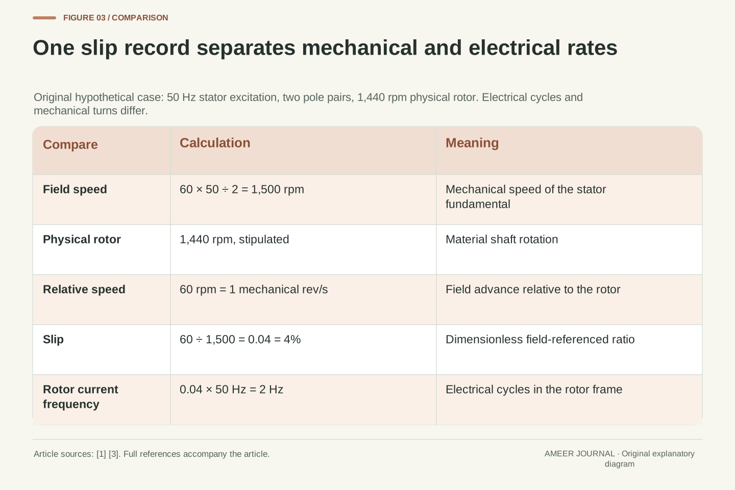
Keep the fifty-hertz, two-pole-pair example, so the stator pattern travels at 1,500 rpm. Now stipulate that an induction rotor turns at 1,440 rpm. The difference is 60 rpm. To express slip, divide that difference by the field speed: 60 ÷ 1,500 = 0.04, or 4%. The rotor is therefore turning at 96% of the field speed. Four percent is chosen for this calculation, not offered as a normal figure for EV motors. [1][3]
The denominator matters. Dividing 60 by 1,440 gives about 4.17%, which describes the gap relative to the rotor’s speed. That is a possible comparison, but it is not the standard slip quantity used here. Likewise, 60 rpm is a speed difference, while 4% is a dimensionless ratio. They cannot replace one another in a formula without bringing the reference speed along. [1][3]
This example supplies the rotor speed as an input. It has not predicted that a real motor would settle there under a given load. To make that prediction, we would need the machine’s electrical and mechanical conditions. What the calculation does establish is internal consistency: 1,500 × (1 − 0.04) returns 1,440 rpm, so the two speeds and the stated slip describe the same hypothetical operating point.
For the positive-speed case, define s = (n_s − n_r)/n_s = 1 − pΩ_m/ω_e, where Ω_m is the rotor mechanical angular velocity. MIT’s induction notes and the native MathWorks expression agree on this pole-pair convention. With n_s = 1,500 rpm and n_r = 1,440 rpm, s = 60/1,500 = 1/25. The dimensionless slip is 0.04, the percentage slip is 4%, and n_r/n_s = 24/25. [1][3]
Using the rotor speed as denominator instead produces 60/1,440 = 1/24, approximately 0.041667. That alternative normalization is not interchangeable with s. A formula containing s expects the field-referenced fraction, not an rpm difference and not a percentage written as the number four. Thus n_r = (1 − s)n_s requires s = 0.04 in this case. Substituting four would be a unit/convention error before any motor physics was considered. [1][3]
This is a consistency calculation, not a solved operating point. We have specified f, p and n_r, then derived s. A physical prediction would require sufficient excitation, a corresponding torque characteristic and a load balance. The example deliberately makes no inference that four-percent slip is typical, optimal, a fault threshold or a control target. Its value is to give every later frequency and power calculation the same explicit reference.
Two hertz of rotor current is not two shaft revolutions per second
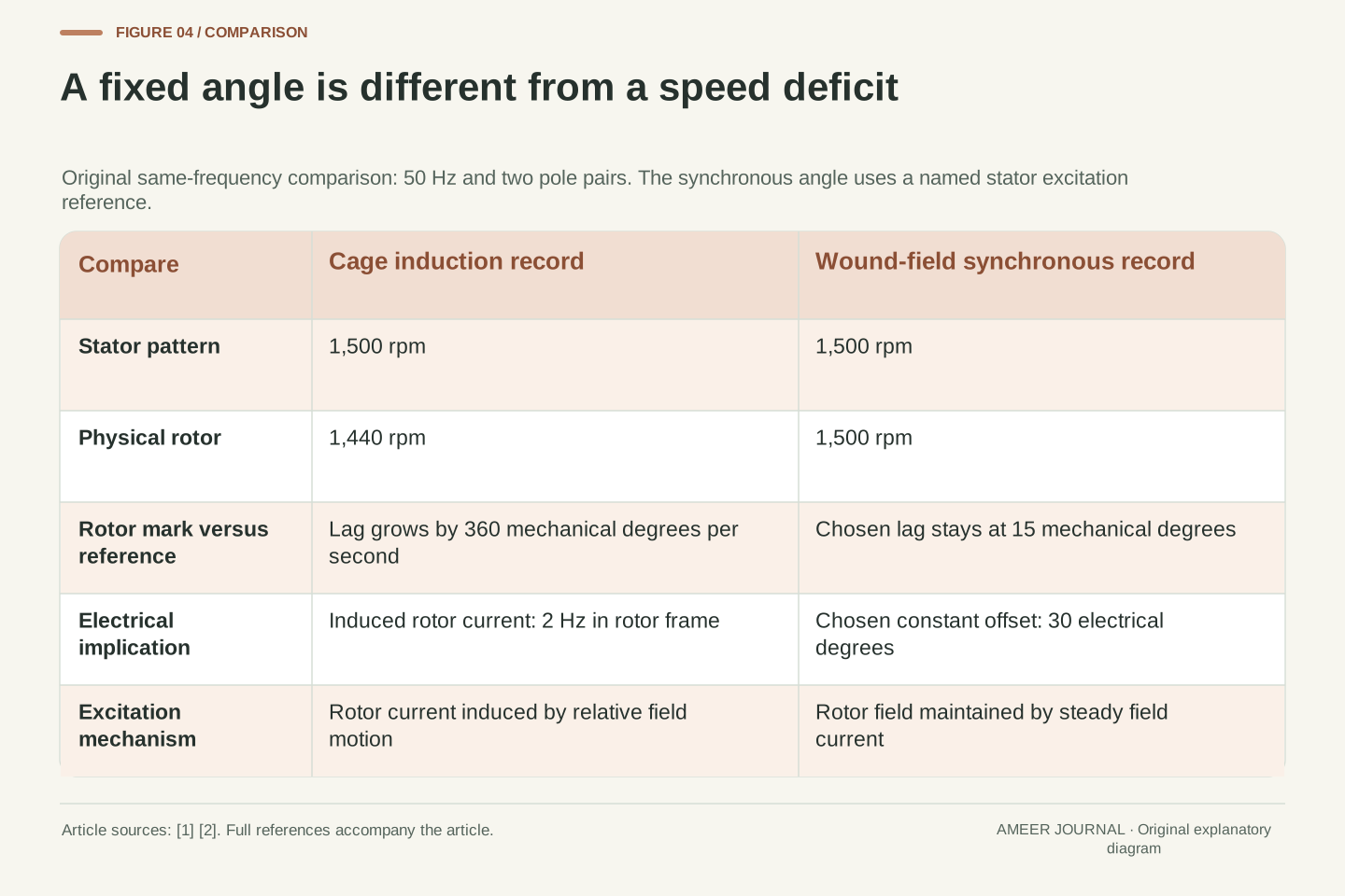
The field gains one mechanical revolution on the rotor each second: the 60 rpm difference is 60 ÷ 60 = 1 revolution per second. Yet the induced rotor current changes through two electrical cycles each second. Why two? There are two pole pairs. During one relative mechanical revolution, the rotor passes through both electrical pattern repetitions. The rotor-frame current frequency is therefore 2 Hz, also found by multiplying 4% slip by the stator’s 50 Hz. [1]
That current does not have the same fixed spatial pattern as paint on the rotor. In the ideal fundamental model, its distribution progresses around the rotor at 60 rpm relative to the metal. The metal already turns at 1,440 rpm relative to the stator. Add the two motions and the current pattern travels at 1,500 rpm in the stationary frame, matching the stator pattern’s speed. [1]
There is no contradiction between a slower rotor and matching field patterns. A material mark follows the metal at 1,440 rpm; a peak in the changing current distribution follows a different rule. Statements such as ‘the rotor field is synchronous’ need that distinction. They can describe a rotating electrical pattern without claiming that the physical cage itself has caught up with the stator’s excitation wave. [1]
The rotor-frame electrical frequency follows f_r = sf = f − pn_r/60. In the chosen case it is 0.04 × 50 = 2 Hz. The relative mechanical speed is only (n_s − n_r)/60 = 1 revolution per second. The factor p = 2 links them. Forgetting that factor would incorrectly identify one mechanical relative revolution with one electrical cycle. MIT expresses the same relationship as ω_R = ω_e − pΩ_m. [1]
The current-wave frame transformation explains the apparent paradox. A rotor-frame fundamental has phase sω_e t − pθ′. With θ′ = θ − Ω_m t and pΩ_m = (1 − s)ω_e, this becomes ω_e t − pθ in the stationary frame. Thus the current distribution rotates mechanically at f_r/p = 1 revolution per second relative to the rotor, or 60 rpm, while its stationary-frame pattern speed is 1,440 + 60 = 1,500 rpm. [1]
The distribution and its conductors must not be merged into one object. A tagged material point remains fixed in rotor coordinates and falls behind the stator wave at 360 mechanical degrees per second in this example. A constant-phase point of the ideal induced current wave does not. The synchronous stationary-frame relationship belongs to the electromagnetic pattern; it is entirely compatible with positive mechanical slip of the cage. [1]
A synchronous rotor can keep an angle without losing speed
For the synchronous comparison, use a rotor field maintained by a steady field current, as in the MIT model. In balanced synchronous operation, the rotor and the rotating stator excitation reference turn at the same speed. They need not point in the same direction at each instant. A constant angle between them can coexist with constant torque. Equal speed means that their angle difference stops changing; it does not require that difference to be zero. [2]
At 1,500 rpm, each reference turns through 9,000 mechanical degrees per second. Choose a rotor axis that stays fifteen mechanical degrees behind the stator excitation reference. After any elapsed time, both have advanced by the same amount, leaving the same fifteen-degree gap. With two pole pairs, this chosen gap corresponds to thirty electrical degrees. It is an angle offset, not a thirty-rpm or fifteen-rpm speed deficit. [2]
The angle must also be named carefully. Here it compares the chosen stator excitation pattern with the rotor field axis. It is not automatically the phase difference between terminal voltage and current. MIT warns that more than one angle can be called a torque angle. The model also has a finite torque capability: keeping synchronous speed is a condition of the stated operating case, not a promise under any load. [2]
The comparison is a balanced sinusoidal wound-field synchronous machine with constant rotor field current. In the source model, pφ = ω_e t + δ_i and the developed torque is proportional to −sin δ_i for fixed excitation amplitudes. A constant nonzero δ_i therefore supports constant torque while pΩ_m = ω_e. This is the declared model’s angle convention, not a universal torque law covering every synchronous rotor geometry. [2]
Define an unwrapped stator excitation-reference angle θ_s(t) = 9,000t degrees and a rotor field-axis angle θ_r(t) = 9,000t − 15 degrees, with t in seconds. Both derivatives are 9,000 degrees per second, equivalent to 1,500 rpm. Their mechanical difference is −15 degrees and their electrical difference p(θ_r − θ_s) is −30 degrees. The offset is constant; it has no units of speed. The reference is the stator excitation/current pattern, not an unspecified resultant air-gap flux axis. [2]
If operating conditions change, a different steady torque may correspond to another permissible relative angle for given excitation. The existence and stability of that operating point remain separate questions. MIT’s finite maximum-torque discussion prevents treating synchronism as unlimited load accommodation. It also distinguishes the excitation angle from other phasor angles: terminal power factor cannot be read directly from the chosen fifteen-degree mechanical offset. [2]
A speed formula is not a complete load calculation
Knowing a motor’s speed relationship does not tell us how much torque it can deliver there. A steady shaft needs its developed torque to balance the opposing load and mechanical losses. For an induction motor, the available torque depends on its electrical conditions and construction as well as slip. The four-percent calculation did not provide those conditions, so it cannot establish a load rating. [1][3]
It is also risky to turn one part of a torque-speed curve into a rule for the whole curve. Nidec describes a particular stable region of a low-impedance induction motor where a load increase causes a relatively small speed decrease. That bounded observation does not mean every induction motor holds exactly constant speed, or that increasing slip always increases torque without limit. Its discussion also notes that torque and current are not simply proportional everywhere. [5]
For the synchronous model, a steady load change can be associated with a changed excitation angle while synchronous speed remains the operating condition. Again, excitation and torque limits matter. These two responses explain why a specification sheet should distinguish electrical frequency, shaft speed and mechanical output. A speed number alone cannot serve as a substitute for all three. [2][3]
The relation n_r = (1 − s)n_s is kinematic. To solve an operating point, it must be combined with electromagnetic torque, load torque and mechanical-loss behavior. In steady rotation the net accelerating torque is zero. The induction equivalent circuit links torque to excitation and its parameters; specifying slip alone does not determine the required current, terminal voltage or a permissible continuous output. [1][3]
A local characteristic is not a global law. Nidec’s statement about relatively small speed reduction with load is explicitly associated with the region to the high-speed side of maximum torque for the described low-impedance machines. It does not justify a universal linear torque-slip relation, an unlimited positive slope or exact load-independent speed. The same source explicitly rejects a generally linear torque-current relationship. Those qualifications matter when interpreting a simplified explanatory curve. [5]
In the wound-field synchronous comparison, constant frequency fixes the synchronous angular velocity, while a permitted steady relative angle and excitation support the required torque. A transient adjustment or loss of that operating condition is outside the constructed steady comparison. Mechanical power then needs torque and angular velocity together. MathWorks correspondingly distinguishes rated mechanical power, rated speed and rated supply frequency instead of representing them with one interchangeable motor number. [2][3]
Slip divides air-gap power before shaft losses are counted
Slip also has an energy-account meaning in the classical induction model. Air-gap power is the electrical power transferred magnetically from the stator side to the rotor. It is not yet the final shaft output. Of that transferred power, a fraction equal to slip is dissipated in the rotor’s resistance. The remainder becomes converted mechanical power before downstream mechanical losses are subtracted. [1]
Assign 100 kW of air-gap power to the four-percent-slip example. The rotor resistance receives 0.04 × 100 = 4 kW, leaving 96 kW converted mechanically. These are power rates at one steady operating point. The four-percent result does not say that four percent of battery energy is lost in the whole vehicle, because neither the battery boundary nor every other motor loss is included in this part of the account. [1]
The torque calculation agrees when its boundaries are kept matched. Divide the 100 kW air-gap power by the field’s angular speed, or divide the 96 kW converted power by the rotor’s angular speed. Both give about 636.6 N·m of developed torque. Mixing the air-gap power with the slower rotor speed would skip the rotor resistance loss and produce the wrong result. The equal answers are a useful check on the complete model. [1]
For the stated steady cage model, rotor resistive dissipation is P_rotor = sP_ag and converted mechanical power is P_conv = (1 − s)P_ag. MIT derives these boundaries from the equivalent circuit’s air-gap transfer and physical rotor resistance. P_ag is a time-average real power crossing that boundary; it is neither automatically terminal input nor final shaft output. [1]
With P_ag = 100,000 W and s = 1/25, P_rotor = 4,000 W and P_conv = 96,000 W. The associated speeds are Ω_s = 50π rad/s and Ω_m = 48π rad/s. Consequently T_e = P_ag/Ω_s = 100,000/(50π) = 2,000/π N·m. Independently, P_conv/Ω_m = 96,000/(48π) gives the same value, approximately 636.620 N·m. Their agreement follows from Ω_m = (1 − s)Ω_s. [1]
The torque is the developed electromagnetic torque in this energy account. It should not be relabelled as delivered shaft torque after unspecified mechanical losses. Dividing P_ag by Ω_m would instead assign the rotor’s resistive dissipation to mechanical conversion. The boundary mismatch survives even if all the numbers look plausible. Separating transfer, dissipation and conversion makes the reason for the two correct torque expressions visible. [1]
Why ninety-six percent is not the whole motor efficiency
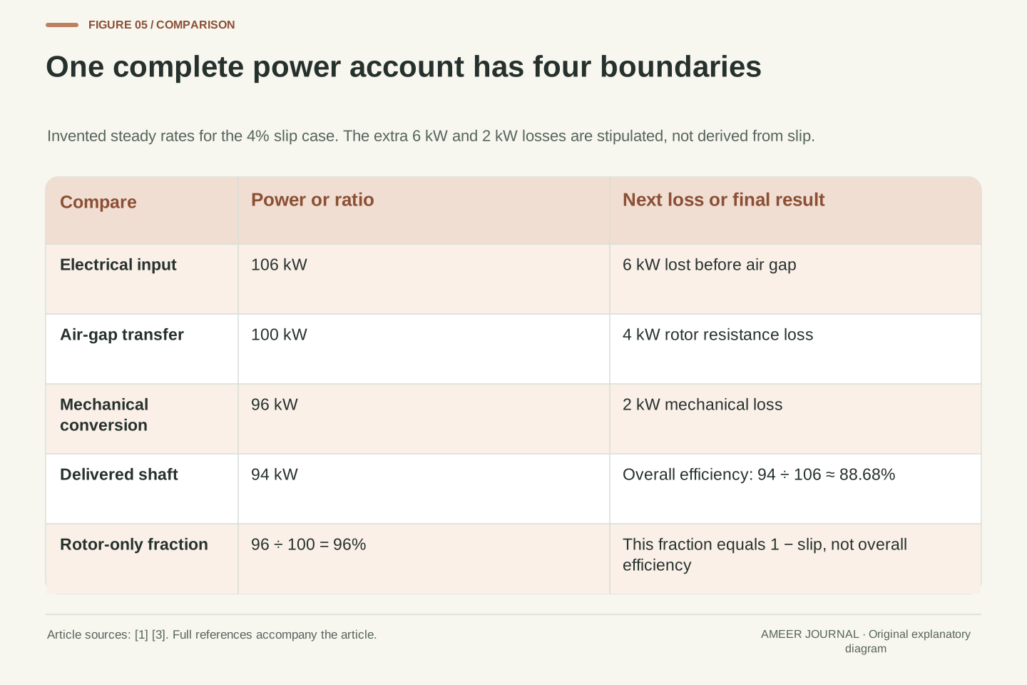
Extend the same invented record with two additional loss allowances. Let the motor receive 106 kW electrically and lose 6 kW before the air gap, leaving the stipulated 100 kW transfer. Rotor resistance takes 4 kW, leaving 96 kW converted mechanically. Let a further 2 kW be lost mechanically before useful shaft delivery. The shaft then supplies 94 kW. Each subtraction belongs at its own boundary. [1][3]
The full account closes: 6 + 4 + 2 = 12 kW of losses, and 106 − 12 = 94 kW of output. Overall efficiency for the stated electrical-input-to-shaft boundary is 94 ÷ 106, approximately 88.68%. Meanwhile, 96 ÷ 100 = 96% is only the rotor conversion fraction from air-gap power. Both percentages are valid descriptions of this record, but they answer different questions. [1][3]
The mechanical loss also separates developed torque from delivered torque. At the same 1,440 rpm, 94 kW of shaft power corresponds to about 623.4 N·m, below the earlier 636.6 N·m developed internally. Slip alone did not reveal the invented six-kilowatt and two-kilowatt losses. That is why a motor’s speed difference cannot, by itself, establish its overall efficiency or compare the efficiency of two complete drive systems.
Add stipulated losses without changing the preceding rotor operating point. Let P_in = 106 kW, with 6 kW dissipated before the 100 kW air-gap boundary. Rotor resistive loss remains 4 kW, leaving P_conv = 96 kW. A separate 2 kW mechanical-loss allowance gives P_shaft = 94 kW. No energy storage changes in this steady account; the three loss terms sum to P_in − P_shaft = 12 kW. [1][3]
The overall defined efficiency is η = P_shaft/P_in = 94/106 = 47/53 ≈ 0.886792. The rotor conversion fraction is P_conv/P_ag = 96/100 = 24/25. Thus 1 − s describes this intermediate fraction, not overall efficiency. The missing losses do not disappear because the rotor-speed ratio also equals 24/25. Numerically equal ratios can have different physical numerators and denominators, and neither one supplies the missing input-to-shaft account. [1][3]
At Ω_m = 48π rad/s, the delivered shaft torque is 94,000/(48π) ≈ 623.357 N·m, compared with developed torque 2,000/π ≈ 636.620 N·m. The reduction represents the stipulated downstream mechanical loss. The 6 kW and 2 kW quantities are independent assumptions here, not results inferred from slip. A different set would change whole-motor efficiency while leaving the earlier speed and rotor-conversion ratios unchanged.
The same shaft speed can belong to two different electrical records
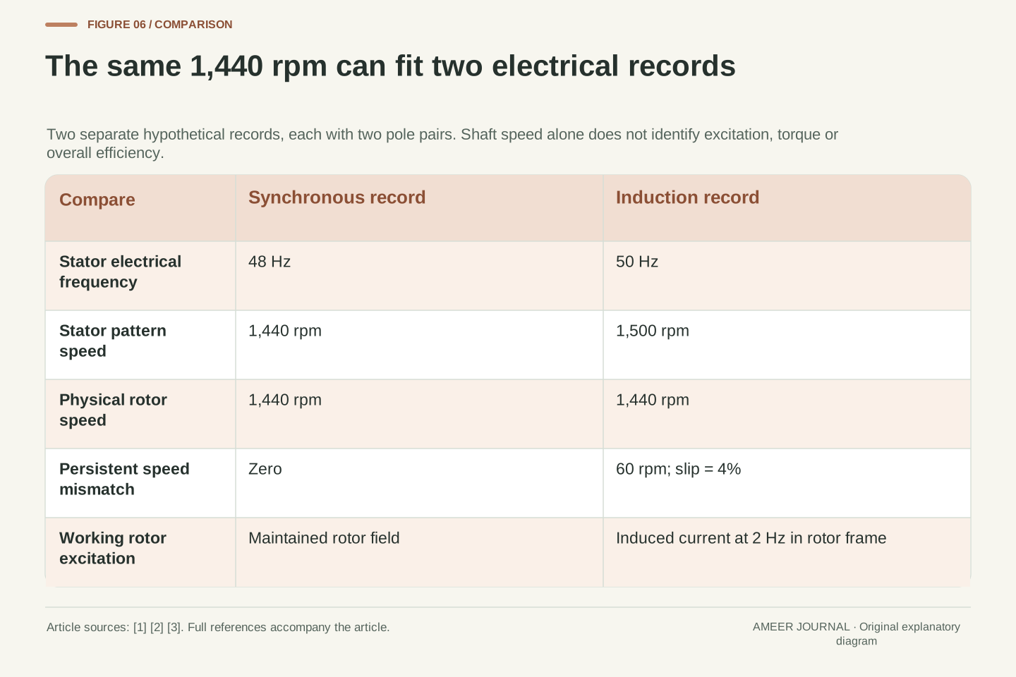
Reverse the comparison: hold physical rotor speed at 1,440 rpm and retain two pole pairs. A synchronous model at that speed requires an excitation frequency of 1,440 × 2 ÷ 60 = 48 Hz. Its rotating excitation reference and rotor have the same mechanical speed. The induction example reaches the same 1,440 rpm with a 50 Hz stator pattern and four-percent slip. These are two different electrical records with the same shaft-speed number. [1][2]
The induction record also contains the 2 Hz rotor-frame current frequency derived earlier. That does not mean its supply is 2 Hz, and it does not mean its shaft turns twice per second. The synchronous record has no persistent speed mismatch between its reference and rotor, yet its maintained rotor field can still support torque at an appropriate fixed angle. The reason for the two outcomes lies in excitation, not a contradiction in arithmetic. [1][2]
Neither record establishes which motor produces more useful power. For that we would need the torque and loss accounts under comparable conditions. Nor can a reported 1,440 rpm identify the motor type on its own. Matching one displayed quantity is compatible with different hidden mechanisms; the missing frequency and excitation description decide which interpretation fits.
Specify n_r = 1,440 rpm and p = 2, then construct two separate records. For synchronous operation, f = pn_r/60 = 48 Hz and n_s = n_r. For the induction record, f remains 50 Hz, n_s = 1,500 rpm and s = 1/25. Both describe the same physical shaft angular velocity of 48π rad/s, while their stator electrical frequencies differ. This comparison changes frequency deliberately; it is not a claim that the two records share identical inputs. [1][2][3]
In the induction case, f − pn_r/60 = 50 − 48 = 2 Hz is the rotor-frame electrical frequency. In the synchronous case, the corresponding relative frequency is zero because the reference follows the rotor. The latter does not imply zero torque: the selected synchronous model has maintained rotor excitation rather than relying on the cage’s slip-induced current. Reusing the cage’s zero-slip torque conclusion across architectures would confuse the induction mechanism with a general speed identity. [1][2]
The inverse problem is consequently underdetermined by rpm alone. Even adding pole count still leaves the excitation frequency and rotor mechanism unspecified. The two constructed records provide an explicit counterexample to identifying those quantities from the shaft number. They also leave torque and efficiency undetermined until further electrical, mechanical and loss information is supplied.
Read speed, angle and power as separate fields
A clear motor description first names the object that is moving. Is a number about the physical shaft, a stator magnetic pattern, or an induced current pattern? It should then say which frame and units apply. In the worked induction case, 1,440 rpm, 1,500 rpm, a 60 rpm difference, 4% slip and 2 Hz of rotor current all belong together. None is a substitute label for all the others. [1][3]
Next, check whether the document supplies total poles or pole pairs and whether its frequency is electrical or mechanical. For a synchronous explanation, ask which two axes define an angle and whether that angle is constant. For an induction explanation, ask whether a quoted slip is a stipulated example, a defined operating measurement or a result of a solved model. This avoids treating a convenient percentage as a universal characteristic. [1][2][5]
Finally, attach every power or efficiency figure to its boundary. Electrical input, air-gap transfer, converted mechanical power and delivered shaft power occupy different places in the account. Understanding the motor family tells you how torque can arise; it does not replace the conditions needed to quantify output. With these fields kept separate, a small difference in rpm becomes an explanation of the mechanism instead of a misleading verdict about performance. [1][3]
A useful record contains an excitation definition, pole-pair convention, named reference frame, mechanical shaft speed and operating assumptions. For the induction example, the internally consistent set is f = 50 Hz, p = 2, n_s = 1,500 rpm, n_r = 1,440 rpm, s = 0.04 and f_r = 2 Hz. A rotor-current wave at synchronous speed in the stator frame adds information about the distribution, not another physical rotor speed. [1][3]
Angle data need similar care. A constant rotor-to-excitation displacement differentiates synchronous tracking from persistent relative mechanical motion; it does not automatically describe terminal voltage-current phase. Nor should a locally described torque-speed characteristic be extrapolated beyond its stated region or used without machine parameters. Equations become informative only after their symbols, normalization and operating domain have been identified. [1][2][5]
Complete the interpretation with the energy boundaries: P_in, P_ag, P_conv and P_shaft are different rates. Their ratios answer different efficiency questions, and their matching angular speeds determine which torque expression is valid. That separation is the practical result of the comparison. It lets a reader reconcile frequency, slip, field motion and shaft delivery while recognizing exactly which additional evidence a performance claim still needs. [1][3]
Sources & further reading
Explore the references behind this guide. External pages may change after our review.
- 6.061 Class Notes Chapter 10: Analytic Design Evaluation of Induction MachinesMIT OpenCourseWare / James L. Kirtley Jr. · Accessed 7 Nov 2026
- 6.061 Class Notes Chapter 9: Synchronous Machine and Winding ModelsMIT OpenCourseWare / James L. Kirtley Jr. · Accessed 7 Nov 2026
- Simplified Induction Motor - Induction motor powered by ideal AC supply - MATLABMathWorks · Accessed 7 Nov 2026
- 2-3-2 Rotation Principle of Induction Motor | Small-size and precision motors | NIDEC CORPORATIONNidec Corporation · Accessed 7 Nov 2026
- 2-3-3 Characteristics of Induction Motors | Small-size and precision motors | NIDEC CORPORATIONNidec Corporation · Accessed 7 Nov 2026
Article updated 7 Nov 2026.
Found something we should revisit?
Good explanations get better with thoughtful feedback.