What you’ll take away
- An isolated pinhole image point defines a viewing ray; a surface or other information is needed to choose a depth.
- Camera intrinsics, installed pose and the assumed road plane play different roles in a ground-distance mapping.
- In the original example, one pitch mismatch creates different distance errors at different points along the road.
- A crop or resize can preserve geometry when the image coordinates and intrinsic parameters are transformed consistently.
- A fitting residual or clear image has a defined scope; actual vehicle checks belong to the applicable manufacturer procedure.
A clear picture and a correct distance answer different questions
A road marking can look sharp in a car-camera image while a calculation places it at the wrong distance. Sharpness tells us something about the appearance of the recorded edge. A distance calculation also needs to know how the camera turns a direction into an image position, where the camera sits, and which surface contains the point. Camera geometry references treat these as separate pieces of information. [1][3][4]
This matters when interpreting the word calibration. Making an image look neat does not establish every relationship used by a driving-support function. A mounting angle, a height above the road and an image-coordinate system each contribute to the result. A plausible-looking overlay can therefore agree with an internal model while the model’s assumptions differ from the scene. We will show that through geometry, without inferring a fault from any actual car’s display.
Every number below belongs to an invented, stationary camera above a perfectly flat surface. Its ideal image has no lens distortion, motion or timing effects. We examine one point at a time and call its horizontal distance forward from the camera D. The examples explain how a mapping can go wrong; they are not a vehicle calibration procedure, a product test or a way to certify a real camera.
Image sharpness and metric projection accuracy are different properties. Even an ideal, noise-free image can be interpreted with the wrong world-to-camera transformation or scene constraint. The pinhole model separates intrinsic image geometry from extrinsic rotation and translation, while a monocular ground mapping additionally assumes a road plane. Those dependencies remain present when the image appears visually clean. [1][3][4]
Our question is therefore narrower than whether a camera works well: when does an image coordinate determine the intended forward ground distance? A mismatch can occur in the assumed pose, the plane intersection or the coordinates supplied to the inverse mapping. We will change those premises separately. This isolates their consequences instead of attributing every incorrect distance to lens quality, pixel count or a visibly distorted frame.
Define an original static, zero-skew, distortion-free pinhole model with no yaw or roll and a flat ground plane. All values are invented. D denotes horizontal forward displacement in the stated world frame, rather than slant range or depth along a pitched optical axis. No camera, vehicle, calibration solver or driving-support controller was tested. The calculations establish conditional geometry, leaving real-system validation to its actual configuration and required procedure.
Keep image scale, camera pose and the road surface separate
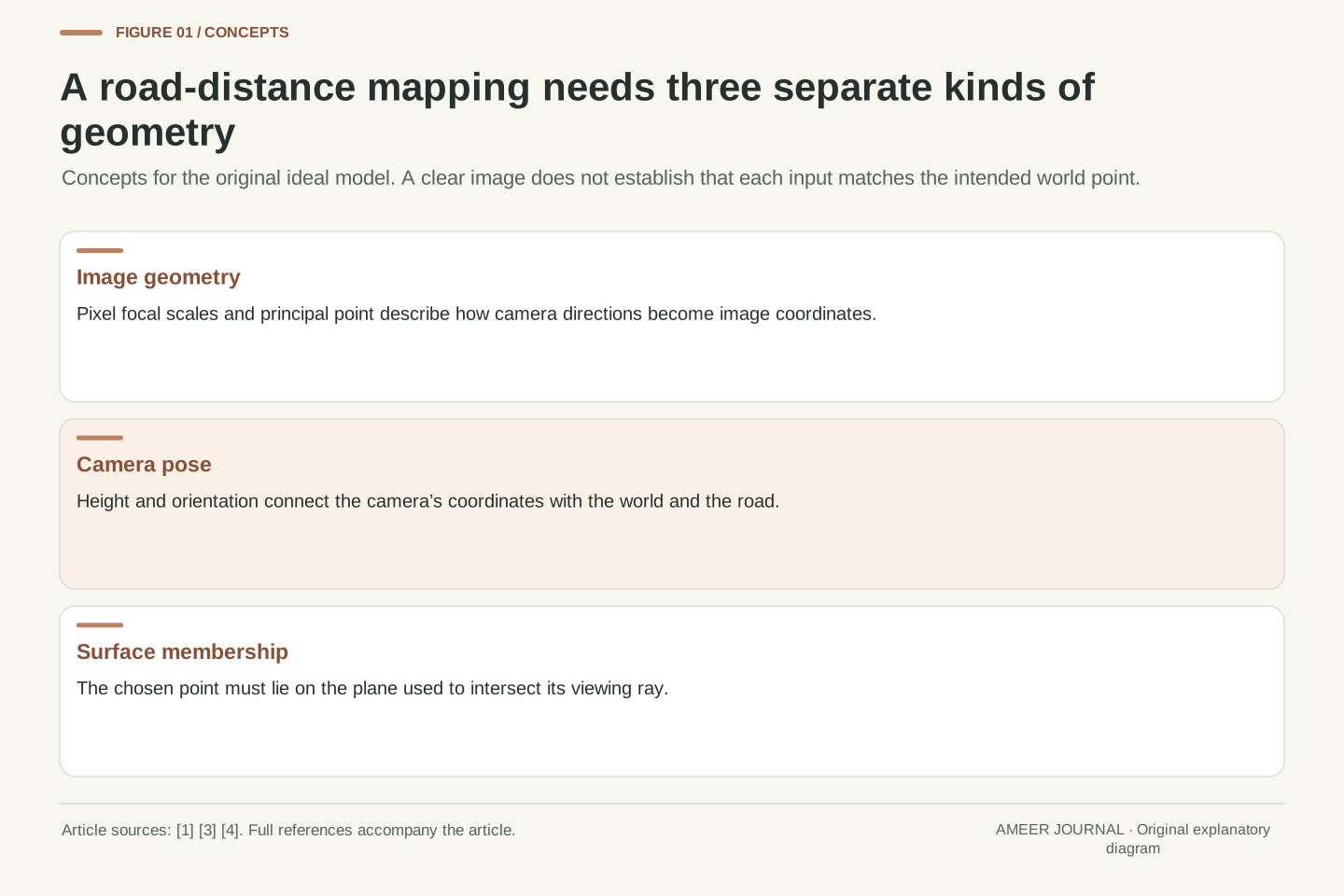
The camera’s internal image geometry includes a scale for each image direction and a reference point called the principal point. In our ideal model, that point is where the optical axis meets the image plane. The vertical scale is expressed in pixels, so a value such as 900 means a conversion between direction and image coordinates; it is not a 900-millimetre physical lens. OpenCV and NVIDIA’s pinhole references make the pixel units explicit. [1][4]
Pose describes the camera’s position and orientation relative to the world. Height above the ground and downward pitch belong here. MathWorks’ monocular-camera documentation lists these separately from the internal image parameters. [3] Rotating the entire camera changes its view of the road even when its internal settings stay fixed. Conversely, changing the coordinates of an already recorded image can alter the numbers used by software without physically moving the camera.
The surface is a third ingredient. A road-plane calculation assumes that the selected point lies on that plane. A point on a raised object follows a different intersection question. Lens distortion adds another part to a real image model, but we set it aside here. [1] Keeping these categories visible prevents a successful correction in one category from being mistaken for evidence that the others are correct.
Use intrinsic parameters f_y and c_y for vertical focal scale and principal-row coordinate. In the zero-skew pinhole model, v = c_y + f_y Y_c/Z_c, with f_y and c_y in pixel units and Y_c/Z_c dimensionless. The principal point is the optical-axis intersection with the ideal image plane. Its coordinates are not guaranteed to equal the geometric centre of every processed image. [1][4]
Extrinsics map world coordinates into camera coordinates through rotation and translation. For our construction, place the world origin at the camera centre, with Y downward and Z forward when the camera is level; X points right. The ground is Y = H. A later pitch rotates the camera axes about the same centre. This convention is explicitly ours, rather than the different vehicle-axis convention in the MathWorks documentation. [1][3]
A scene-plane constraint then selects one point on a viewing ray. Intrinsics, pose and plane are conceptually separate even when a practical estimation method solves several together. Lens-distortion parameters extend the image-formation model but do not substitute for a correct camera-to-road pose. [1][3] We use an already ideal image throughout, so any distance error we derive exists without requiring a radial-distortion error.
One image point can belong to several positions in space
A single point in a pinhole image identifies a direction from the camera. Several positions along that direction can share the same image coordinate. [1] Picture two possible scene points, considered separately: one is one metre below the camera and fifteen metres forward; the other is two metres below and thirty metres forward. Both have the same downward-to-forward ratio, one to fifteen. Their different distances have disappeared from that ratio.
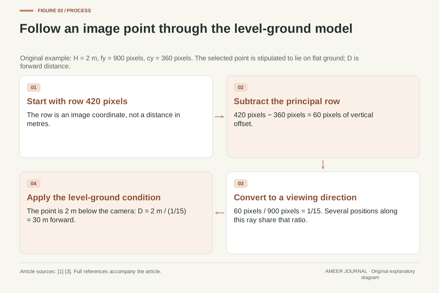
Give our level camera a height of two metres, a vertical image scale of 900 pixels and principal row 360. Both possible points appear at row 420: multiply one-fifteenth by 900 and add 360. Yet only the second point lies on the stipulated ground, two metres below the camera. The first point is one metre above that ground. Calling both points ground points would assign the first an incorrect forward distance.
This is why the identity of the chosen image feature matters. A model can intersect its viewing direction with a known flat surface, as the monocular road mapping describes. [3] It cannot make an arbitrary elevated feature lie on that surface simply because the feature is clear. Other information can resolve depth, but the isolated pixel and the pinhole projection alone have not supplied it.
The pinhole projection is invariant under positive scaling of a camera-space position: Y_c/Z_c remains unchanged when both coordinates receive the same factor. OpenCV explicitly connects this to all points along a ray sharing one image position. [1] The ambiguity concerns the isolated projection, not a claim that every complete vision system lacks additional depth information from other observations or constraints.
For the level model, set H = 2 m, f_y = 900 pixels and c_y = 360 pixels. Points (X,Y,Z) = (0,1,15) m and (0,2,30) m both have normalized vertical coordinate 1/15 and v = 420 pixels. Their heights above the ground are H−Y: respectively 1 m and 0 m. A ground intersection at the latter position does not identify the former point’s actual depth.
A flat-road assumption supplies Y = H and selects a forward intersection when the ray geometry permits one. [3] Applying that constraint to a point on a raised object changes the problem being solved. Feature location, pose and surface membership must therefore accompany the reported distance. Our example distinguishes a forward coordinate from an image label without needing an object-size estimate, an occlusion model or any fabricated detection result.
Start with the level-camera distance rule
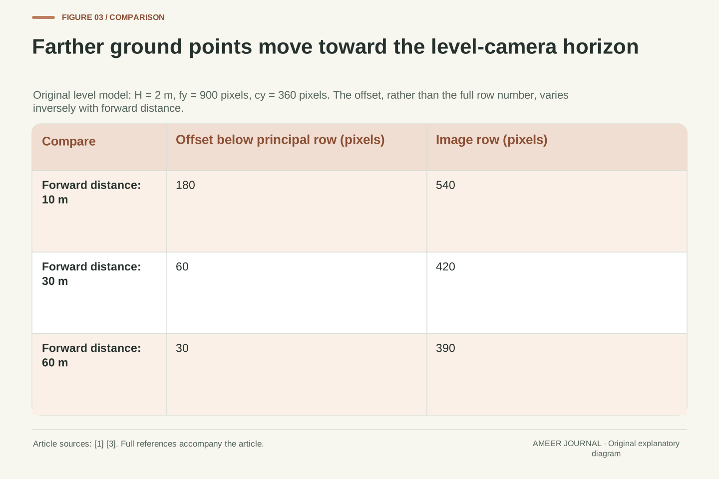
For a point on our flat ground, the downward distance from the camera is always two metres. A point farther forward therefore makes a shallower downward direction. The image-row offset below the principal row equals 900 times two divided by its forward distance. That is a direct use of the pinhole relationship with the ground assumption added. [1][3] The image coordinate moves closer to row 360 as the ground point gets farther away.
At ten metres forward, the offset is 180 pixels, giving row 540. At thirty metres it is sixty pixels, giving row 420. At sixty metres it is thirty pixels, giving row 390. Doubling the thirty-metre distance halves the offset; it does not halve the complete row number. The reference row must be subtracted before the ratio is used. Otherwise the calculation mixes a position with a displacement from the reference.
To work backward, multiply the 900-pixel scale by the two-metre height and divide by the row offset. Row 420 gives 1,800 divided by sixty, or thirty metres. The answer is forward distance along the level ground. The diagonal line from the camera to that point is longer, so a number described simply as camera distance would leave an avoidable ambiguity about what was calculated.
With level pose, Y_c = H and Z_c = D for a forward ground point. Substitution gives v−c_y = f_y H/D and therefore D = f_y H/(v−c_y), for D>0 in the selected ground geometry. [1][3] Dimensions close: pixels times metres divided by pixels yields metres. H is the perpendicular ground-to-camera-centre separation, while D is the horizontal forward coordinate.
The original parameter product f_y H is 1,800 pixel-metres. D = 10, 30 and 60 m therefore produces offsets 180, 60 and 30 pixels, and rows 540, 420 and 390. These examples also show why using v rather than v−c_y is incorrect: the principal-point origin is part of the mapping. The same projected direction can have a different numeric row after a coordinate translation.
For this level model, the ideal ground horizon approaches v = c_y as D tends to positive infinity. A finite forward ground point has v>c_y. The horizon is a vanishing line of the plane, not necessarily a visible skyline in a real scene. Introducing pitch will move that vanishing line while leaving the camera’s intrinsic principal row unchanged, which is the source of the next distinction.
A downward tilt moves the ground horizon within the image
Now keep the same camera centre and image parameters, but tilt the camera downward. Choose an angle whose tangent is one-sixtieth, about 0.955 degree. That means its optical axis points downward by one unit for every sixty units forward. This small angle is invented for the calculation; it is not a manufacturer’s allowed error. Camera orientation is a separate input to the image-to-road relationship. [1][3]
The optical axis still meets the image at principal row 360. However, because it now points downward, that ray reaches the ground at a finite distance: two metres times sixty, or 120 metres forward. The ideal ground horizon moves fifteen pixels upward to row 345. Principal row and ground horizon therefore no longer mean the same line. Treating the middle reference as the horizon would silently restore the wrong level-camera assumption.
Consider the same ground point thirty metres forward. Before the tilt it appeared at row 420. Under this downward pose it appears at about row 404.95. No blur is required for that change. The point can remain perfectly sharp because the issue is where its viewing direction falls within the frame. A correct inverse mapping must use the changed orientation as well as the unchanged internal image scale.
Let downward pitch be α, with t = tan α = 1/60. In our declared coordinates, a ground point (0,H,D) transforms to Y_c = H cos α − D sin α and Z_c = H sin α + D cos α. This is a rotation about the same camera centre, consistent with the world-to-camera transformation model. [1][4] No physical lens tilt or change of intrinsic matrix is introduced.
The normalized row is r = (v−c_y)/f_y = (H/D−t)/(1+(H/D)t). As D tends to positive infinity, r tends to −t, so the ground horizon is v_h = c_y−f_y t = 345 pixels. At the principal row r=0, the forward ground intersection instead satisfies D=H/t=120 m. These are different geometrical conditions even though both use the same c_y.
For D=30 m, the exact normalized coordinate is r=45/901 and v=364860/901 pixels, approximately 404.9501. The camera-axis depth Z_c also differs from the world-forward D after rotation. Preserving that distinction prevents an otherwise correct projection from being described as the wrong kind of range. The calculation is restricted to the stated forward ground points, whose camera depths remain positive.
The wrong pose does not create one fixed distance offset
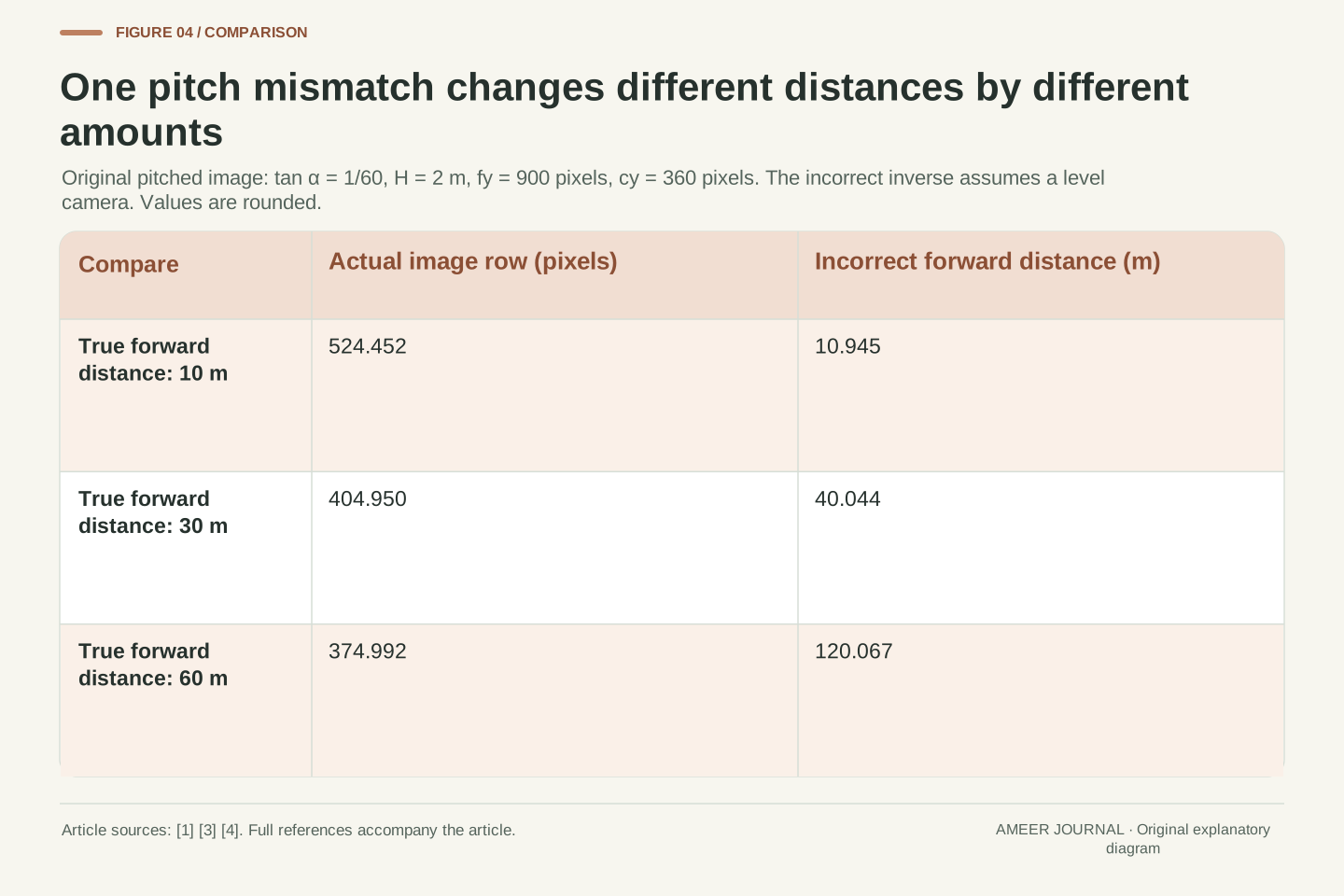
Suppose software receives that tilted image but still uses the old level-camera distance rule. For the thirty-metre point, it subtracts row 360 from about 404.95, then divides 1,800 by the resulting offset. It reports about 40.04 metres. The image position was correct for the tilted camera; the mistake was interpreting it with a different pose. The model’s separate projection and inverse steps make the source of the error visible. [1][3]
The same wrong assumption affects other distances differently. A true ten-metre point would be interpreted as about 10.95 metres forward. A true sixty-metre point would become about 120.07 metres. These are three results from one invented angle mismatch, not three measured faults. Subtracting one fixed number of metres from every answer would not repair this particular pattern because the error grows non-uniformly with distance.
At the optical-axis ground intersection, 120 metres forward, the correct image row is 360. The old level rule would try to divide by a zero row offset even though the tilted geometry has a finite intersection. That is a useful boundary check: an image coordinate has meaning only together with the pose and surface model used to interpret it. A familiar-looking row does not carry a universal distance.
Solving the pitched projection for D gives D = H(1−rt)/(r+t), for the selected forward intersections. Feeding the same r into the incorrect level formula instead gives D_level = H/r. At the true D=30 m, r=45/901, so D_level=1802/45 m≈40.0444 m. The correct pitched inverse returns exactly 30 m. [1][3] The two outputs arise from different geometric assumptions applied to the same coordinate.
The corresponding exact wrong-level results are 602/55 m≈10.9455 m at true D=10 m, and 1801/15 m≈120.0667 m at true D=60 m. A constant additive distance bias cannot represent all three differences. Even a constant multiplicative correction is insufficient: the ratios between inferred and true distance differ across these records. This is a consequence of the fractional dependence on r and t.
At r=0, the correct pitched inverse yields H/t=120 m, while H/r is undefined. This singularity belongs to the incorrectly applied level mapping, rather than proving the scene point is infinitely distant. The examples quantify no actual calibration tolerance or fault probability. They show why parameter compatibility and domain conditions must be checked before a numeric distance can be interpreted as a physical result.
Height errors and row changes follow different rules
Return to the separate level-camera case at row 420. If the calculation assumes a height of 2.4 metres while the actual invented height stays two metres, the inferred distance becomes thirty-six metres. The same image is being interpreted with a height twenty percent too large. In this level model, that height error scales every inferred forward distance by the same factor. It differs from the distance-dependent pitch mismatch we just examined. [1][3]
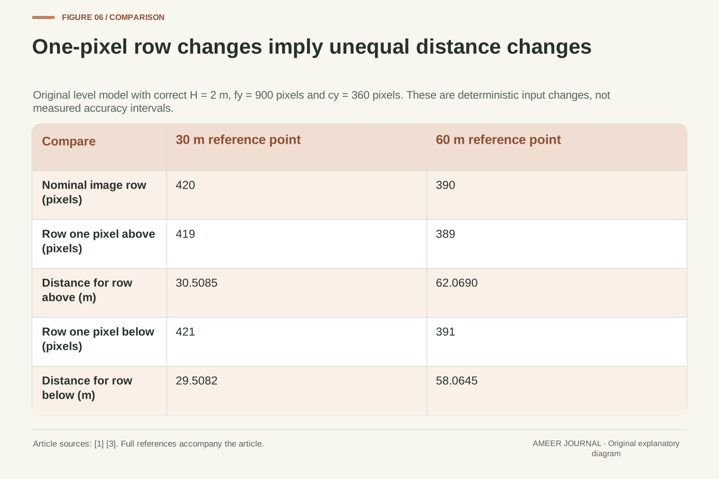
A change in the selected image row has another effect. Keep the correct two-metre height and compare one pixel above and below row 420. Row 419 gives about 30.51 metres; row 421 gives about 29.51 metres. Repeat that one-pixel change around row 390, whose nominal distance is sixty metres, and the results are about 62.07 and 58.06 metres. Equal image-coordinate changes do not imply equal distance changes.
These are deliberate paper changes, not measured camera noise or a claimed accuracy range. They explain why a distance label needs its geometric conditions. Near the level ground horizon, the row offset used as the divisor is smaller, so the same one-pixel change becomes a larger part of that divisor. Adding more decimal places to the final distance does not remove this sensitivity.
With the level image held fixed, D_hat/D = H_assumed/H_true. Using 2.4 m instead of 2 m gives a factor 1.2, hence 36 m at v=420 pixels. This is a separate height-misassignment case, not a second error added to the pitched model. The distinction follows directly from the multiplicative H term in D=f_y H/(v−c_y). [1][3]
For deterministic row perturbations, the finite results around 30 m are 1800/59≈30.5085 m at v=419 and 1800/61≈29.5082 m at v=421. Around 60 m they are 1800/29≈62.0690 m at v=389 and 1800/31≈58.0645 m at v=391. The intervals are slightly asymmetric because the inverse depends on the reciprocal of the row offset.
The local derivative is dD/dv = −f_y H/(v−c_y)²: −0.5 metre per pixel at row 420 and −2 metres per pixel at row 390. These derivatives describe local sensitivity, while the preceding finite changes were calculated exactly. Neither is a standard deviation or confidence statement. A real uncertainty budget would need justified uncertainties in the relevant inputs and their relationships, which this illustrative model does not supply.
A small fitting residual belongs to the points and model that were checked
Calibration can compare known positions in a scene with their recorded image positions. Reprojection means using a proposed camera model to predict where those known points should appear, then comparing the predictions with the observations. OpenCV’s tutorial describes this comparison. [2] It is more informative than judging whether a picture looks tidy, because it asks whether particular numerical relationships agree.
The comparison still has a scope. A model checked against points while the camera was level has not thereby been checked after its mounting angle changes. In our example, the thirty-metre ground point moved from row 420 to about 404.95 when the camera tilted. An old fit result cannot supply the missing evidence that the new pose is correctly represented. Likewise, a point on a raised surface cannot validate the flat-ground distance rule merely by being easy to locate.
Known reference dimensions also matter. The tutorial distinguishes object coordinates in physical units from coordinates expressed in pattern units. [2] The numbers assigned to a reference must mean what the calculation assumes. A useful report therefore identifies the points, coordinate units, image processing and pose being evaluated. A low residual is evidence about that comparison, not a replacement for naming its conditions or checking a different scene model.
A reprojection residual compares an observed image point with the projection of its supplied object-space counterpart under the evaluated camera model. The OpenCV tutorial uses known object and image points for that comparison. [2] This quantifies fit to the chosen correspondences. Identifiability, reference scale and applicability to a later configuration remain separate questions.
For example, a residual evaluated on the level-camera state does not validate the later pitched state while retaining the level extrinsics. Our original point at D=30 m projects to row 420 before rotation and approximately 404.9501 afterward. The pose change affects the predicted image position even with unchanged intrinsics. Similarly, a ground-plane inverse has a surface-membership premise that cannot be established solely by fitting an unrelated set of image coordinates. [1][3]
The supplied object-coordinate scale also determines the units of an estimated translation; OpenCV explicitly distinguishes pattern-size units from specified physical dimensions. [2] A meaningful evaluation record therefore names the reference geometry, correspondence set, coordinate transformations and tested configuration. This article supplies no solver output, residual threshold or validation dataset. Its point is to preserve what the residual compares, so fitting agreement is not silently extended to a different pose, plane or image-coordinate convention.
Cropping changes the coordinate origin even when the scene stays fixed
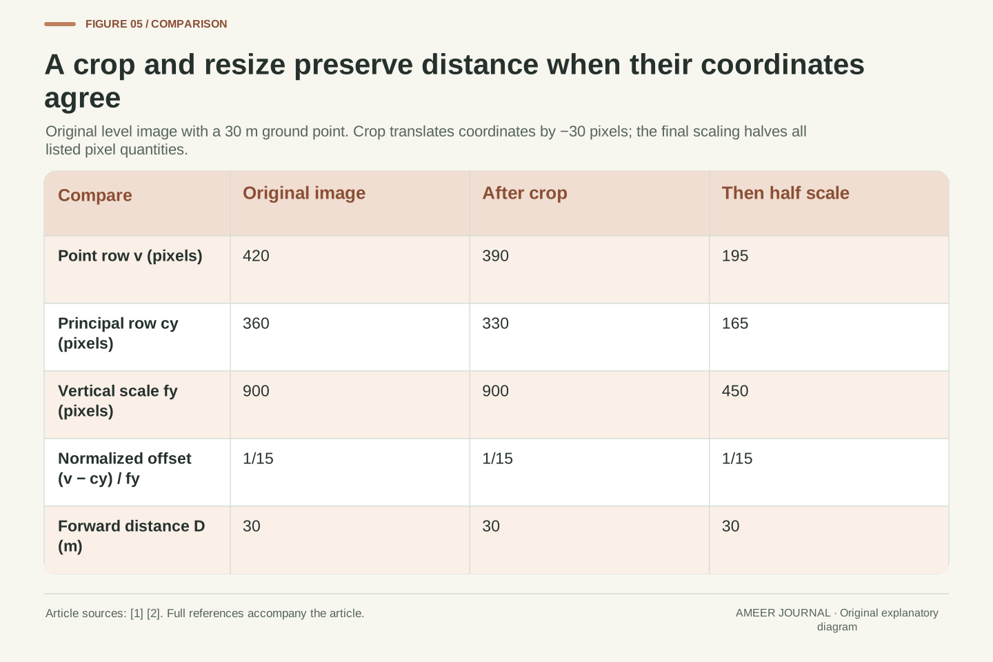
Take the original level image again, with the thirty-metre ground point at row 420 and principal row 360. Crop thirty pixels from the top. In the new image coordinates, the point is at row 390 and the principal point is at row 330. Their difference remains sixty pixels, so the inferred distance stays thirty metres. No camera movement is needed for either row number to change.
If the calculation uses the cropped point row 390 but mistakenly keeps the old principal row 360, it sees an offset of only thirty pixels. The level formula then gives sixty metres. The wrong result came from mixing two coordinate origins, not from a physical doubling of distance. OpenCV’s documentation identifies image scaling and new image matrices as things that must be handled consistently. [1][2]
Now halve all vertical coordinates in the cropped image. The point row becomes 195, the principal row 165 and the vertical scale 450 pixels. The offset is thirty pixels, but the scale has also halved, preserving the viewing direction and the thirty-metre result. These are declared mathematical coordinate changes; an actual image library’s pixel-centre conventions must be accounted for in its own mapping.
Define a continuous image-coordinate translation v_new=v−30 pixels. Its compatible intrinsic origin is c_y,new=c_y−30 pixels, while f_y stays unchanged. Thus the original (v,c_y,f_y)=(420,360,900) becomes (390,330,900), and r=(v−c_y)/f_y remains 1/15. The physical viewing ray and forward-ground intersection are unchanged. This is coordinate bookkeeping derived from the projection, rather than a claim that cropping changes physical pose. [1]
Using the old c_y=360 with the cropped v=390 instead gives r=1/30 and D=60 m. A later declared uniform scaling by one half must transform all three relevant pixel quantities: (195,165,450) again gives r=1/15 and D=30 m. The invariance follows from scaling numerator and denominator together, consistent with the image-scaling requirement in OpenCV’s intrinsic model. [1]
These equations explicitly define the coordinate maps and do not assume a particular resampling library’s pixel-centre alignment. A real undistortion output may also use a newly chosen camera matrix; the OpenCV tutorial distinguishes that matrix and a cropped region. [2] The appropriate parameters therefore belong to the actual image coordinates supplied to the downstream mapping, rather than to whichever earlier image happened to look similar.
An owner manual gives the real vehicle-specific requirement
The geometry explains why a service requirement can extend beyond how the windscreen or camera picture looks. One concrete example appears in Volvo’s Australian EC40 windscreen guidance. The retrieved page, marked updated October 28, 2024, says new glass and its installation must meet Volvo specifications and that the forward-facing camera requires function checks and calibration by a service technician after installation. [5]
That statement belongs to the described vehicle guidance. It does not establish one procedure for every car, and our two-metre camera model is not a substitute for the specified checks. Different equipment and documented requirements must be identified from the applicable vehicle information. The useful connection is that an installed camera participates in a geometric system; a satisfactory appearance cannot by itself confirm all relationships used by that system.
When reading a service record, the meaningful question is which required checks were completed for the particular vehicle and work performed. A screenshot, a sharp image or a generic calibration label leaves that question unresolved. This article offers no adjustment, reset or road exercise. It gives the vocabulary to understand why the applicable check concerns configuration and function as well as visible image quality.
The retrieved Australian EC40 windscreen page provides a bounded operational context. Its displayed update date is October 28, 2024. It requires compatible glass and installation, followed by function checks and calibration of the forward-facing camera by a service technician after windscreen installation. [5] This is a source-specific requirement; no broader service schedule or cross-manufacturer procedure is inferred.
Our mathematical model does not identify the exact parameters, targets, equipment, tolerances or diagnostic steps used in that procedure. It explains why a camera’s installed configuration can matter to a downstream geometric result. Actual verification must correspond to the applicable vehicle and completed work. A demonstration that one image is visually sharp supplies neither the required procedure record nor a quantitative validation of its road mapping.
The service context therefore stays separate from the toy calculation. The retained source supports the existence and scope of the stated professional check, while the original geometry illustrates why appearance is insufficient evidence for metric correctness. Combining those two roles does not turn a hypothetical pitch value into an allowed error, or a computed distance difference into a diagnosis of a real car.
Read the complete meaning of a distance label
Begin with the point being located. Is it actually on the surface assumed by the mapping, or is it higher than that surface? Then identify the distance being reported: forward along the ground, along the camera’s optical direction, or diagonally to the point. Our thirty-metre result always refers to the first of those. A number can be arithmetically correct and still be misleading when its physical meaning is left unnamed.
Next follow the image coordinates and camera pose together. The same ground point kept its real location when a crop changed its row number. The same internal image scale stayed in place when a tilt changed the ground horizon. A wrong height produced a proportional distance error, while a wrong pitch produced a distance-dependent one. These distinct patterns came from different assumptions, so one visual impression cannot identify which assumption is valid.
Finally, ask what evidence supports the mapping’s use in its stated setting. Known points, a fitting result and a vehicle-specific function check each answer a defined question. [2][3][5] Preserve that question when reading the result. The advantage of a clear camera image is that it makes features easier to see; the correctness of a ground-distance estimate still depends on the geometry connecting those features to the world.
A complete distance statement names the image point, its coordinate system, the camera intrinsics and pose, the assumed scene surface, and the output coordinate or range definition. [1][3] In the original examples, D is a world-forward ground coordinate. A raised point, camera-axis depth and slant range cannot be substituted into that label merely because all are expressed in metres.
The algebra provides useful interpretation checks. Height appears as a scale factor in the level inverse; pitch changes the fractional relationship between r and D; coordinate translation changes v and c_y together; uniform image scaling changes their difference and f_y together. The one-pixel examples additionally reveal the reciprocal mapping’s distance sensitivity. Each consequence follows from a specified change, rather than from a generic claim that calibration is either good or bad.
Evidence should then be matched to the claim it evaluates. A reprojection comparison concerns supplied correspondences and a model, a planar mapping concerns a stated surface, and the documented EC40 service requirement concerns a particular installed vehicle context. [2][3][5] Keeping those roles explicit allows a sharp image to be appreciated without treating its appearance as proof of every metric relationship derived from it.
Sources & further reading
Explore the references behind this guide. External pages may change after our review.
- OpenCV: Camera Calibration and 3D ReconstructionOpenCV · Accessed 7 Nov 2026
- OpenCV: Camera CalibrationOpenCV · Accessed 7 Nov 2026
- monoCamera - Configure monocular camera sensor - MATLABMathWorks · Accessed 7 Nov 2026
- VPI - Vision Programming Interface: Pinhole Camera ModelNVIDIA · Accessed 7 Nov 2026
- EC40 Windscreen damage | Volvo Support AUVolvo Cars · Accessed 7 Nov 2026
Article updated 7 Nov 2026.
Found something we should revisit?
Good explanations get better with thoughtful feedback.