What you’ll take away
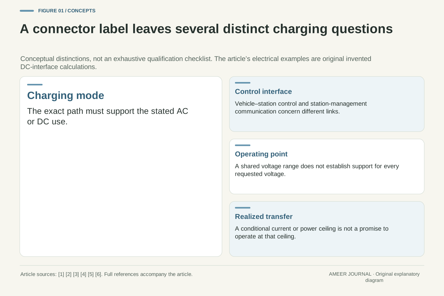
- A connector-family name does not establish every permitted AC or DC use of the complete charging path.
- Vehicle–station control and OCPP station-management communication describe different interfaces.
- Nonempty voltage overlap is weaker than support for the specific requested voltage or the full request window.
- At one DC operating point, compare current limits with the power cap divided by that same voltage.
- A conditional power ceiling, a requested value, a delivered value and a certification claim are different kinds of information.
A matching plug answers only part of the question
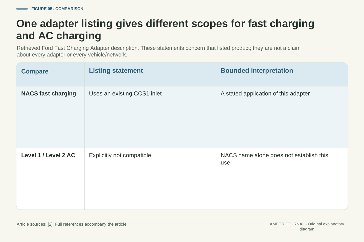
Two charging products can share a connector name without supporting the same use. Ford’s retrieved Fast Charging Adapter listing gives a concrete example: it describes NACS fast-charging networks with an existing CCS1 vehicle inlet, but explicitly excludes Level 1 and Level 2 AC chargers, including NACS home and destination examples. [2] The shared name therefore does not settle the charging mode of the complete connection. A connector label is useful information; it is not a complete compatibility statement.
Standards also have a particular scope. The Joint Office’s October 2024 J3400 announcement discusses hardware and software standards, while SAE’s public April 2025 adapter-report scope covers physical, electrical, functional and performance requirements. [1][6] Neither page is a certificate for any equipment combination in this article. We will use their stated boundaries and an original paper model to separate fitting together, communicating and supplying an allowed electrical operating point.
Every voltage, current and power value in that model is invented. No vehicle, adapter or charging session was tested. The aim is to read a compatibility claim more precisely: identify which question the evidence answers, then keep the unanswered questions visible. Our calculation will establish a conditional power ceiling only after its other necessary conditions have been assumed. It will not turn a matching plug into an approval.
Mechanical compatibility, supported charging mode, control interoperability and an admissible electrical operating point are separate properties. The retrieved Ford adapter listing illustrates why a connector-family name cannot collapse them: it names NACS fast charging into CCS1 while excluding Level 1/2 AC applications using NACS connectors. [2] That is evidence about one product’s declared scope, not a universal adapter taxonomy or a recommendation for a particular vehicle.
The October 2024 Joint Office announcement and SAE’s April 2025 public adapter-report scope likewise address different parts of the standards landscape. [1][6] Only the retained announcement and public scope were read; no paid standard’s complete requirements or latest-edition status is claimed. We will distinguish a documented interface, an implementation and a modeled operating point rather than treating their labels as interchangeable evidence.
The original model stipulates steady DC transfer, exact voltage intervals and constant current/power bounds. All numerical values are invented. Unrepresented protocol, permission, thermal and safety conditions are assumed satisfied where a power calculation is performed; they are not proved by it. This creates a bounded necessary-condition exercise with reproducible arithmetic, not an electrical qualification procedure or a report of equipment testing.
Start with the charging mode and its conversion path
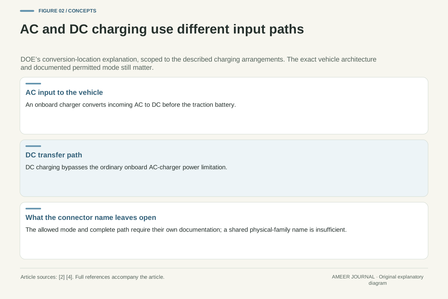
AC and DC describe different forms of electrical supply. In the AC arrangement described by DOE, the vehicle’s onboard charger converts incoming AC to DC before it reaches the traction battery. DOE’s DC-charging explanation instead bypasses that onboard AC-charging limitation. [4] The location and type of conversion matter because two connections with a familiar-looking physical interface can be intended for different paths inside the vehicle.
Imagine a label that says only which connector family appears at each end. That label does not tell us whether the intended supply is AC or DC, whether the vehicle supports that path, or which approved equipment may form the connection. Filling in those missing facts is a documentation task. It cannot be completed by borrowing the power rating from another charger that happens to use a similar connector name.
Our worked example begins after an allowed DC transfer path has been established. Its voltage is the voltage at that transfer interface, not a vehicle’s advertised battery-voltage class. This distinction leaves room for different vehicle architectures: the number at the inlet and a nominal pack label need not describe the same operating quantity. We will keep all the example’s current and power entries at the same interface.
DOE’s 2022 fleet-training transcript describes AC EVSE feeding an onboard AC-to-DC charger, and DC charging that bypasses the onboard AC-charger power limitation. [4] Only that architectural distinction is used here. The transcript’s contemporary market descriptions, charger power examples, circuit requirements and forecasts are not treated as present-day specifications. Nor does bypassing an onboard AC stage imply that every vehicle DC architecture contains no internal power conversion.
Define the modeled boundary at the established DC transfer interface. Let U be its positive voltage and I its transferred current. The scalar power model will be P=UI at this boundary. This is not an AC apparent-power calculation, a battery nominal-voltage conversion or an assertion that all input power becomes stored battery energy. Selecting one boundary avoids combining a current from one stage with a voltage from another.
A compatibility record must therefore identify the allowed mode before evaluating numerical limits. Evidence for an AC use cannot be silently substituted for evidence for a DC use. The hypothetical voltage range introduced later describes possible requested interface voltages under the model’s conditions, not a driver-adjustable setting or the entire behavior of any actual pack. Internal conversion and its losses remain outside the specified account.
Ask which devices a communication label connects
A charging station can take part in more than one conversation. ChargePoint describes continuing communication between the vehicle and station as the vehicle’s conditions and power request are considered. [5] Separately, the Open Charge Alliance defines OCPP as communication between a charging station and its management system. [3] Those descriptions refer to different pairs of participants. A claim about one pair does not, by itself, establish the behavior of the other.
Draw three boxes: vehicle, station and management system. Put the vehicle-control conversation between the first two, and the OCPP management link between the last two. The station appears in both relationships, but that shared box does not make the links identical. For example, knowing that the station can exchange a management message tells us nothing numerical about whether it can provide a particular requested DC voltage.
This is also why a failure message needs careful interpretation. An unavailable session can have several possible unmet conditions; its appearance alone does not identify the connector, controller or management link as the cause. The article does not prescribe a troubleshooting sequence. It separates what a protocol label actually names from extra conclusions that would require implementation-specific evidence. Not every charging arrangement has the same management or authorization requirements.
Keep the vehicle-facing control interface distinct from the station-to-management interface. ChargePoint describes vehicle/station communication during DC charging; OCA identifies OCPP’s endpoints as the charging station and Charging Station Management System. [3][5] These endpoint definitions are enough to reject a common category error: OCPP support is not, by itself, evidence that a particular vehicle-facing protocol, electrical path or connector combination is supported.
In a three-node representation, the station is incident to both relationships. Shared membership does not imply equivalence between the relationships. No message format, handshake order or vehicle-protocol implementation is inferred here. The electrical calculation will likewise supply no evidence about successful control negotiation. A set of admissible scalar values and an interoperable state machine are different kinds of claim, even when both matter to a session.
Do not infer a mandatory live backend transaction for every possible charging arrangement from this diagram. Network and authorization requirements belong to the particular implementation. Conversely, a successful backend exchange does not prove the requested electrical point is available. The useful reading habit is to attach each communication claim to its actual endpoints, version and stated scope before using it as evidence for a larger system.
Overlap at some voltage is different from support at this voltage
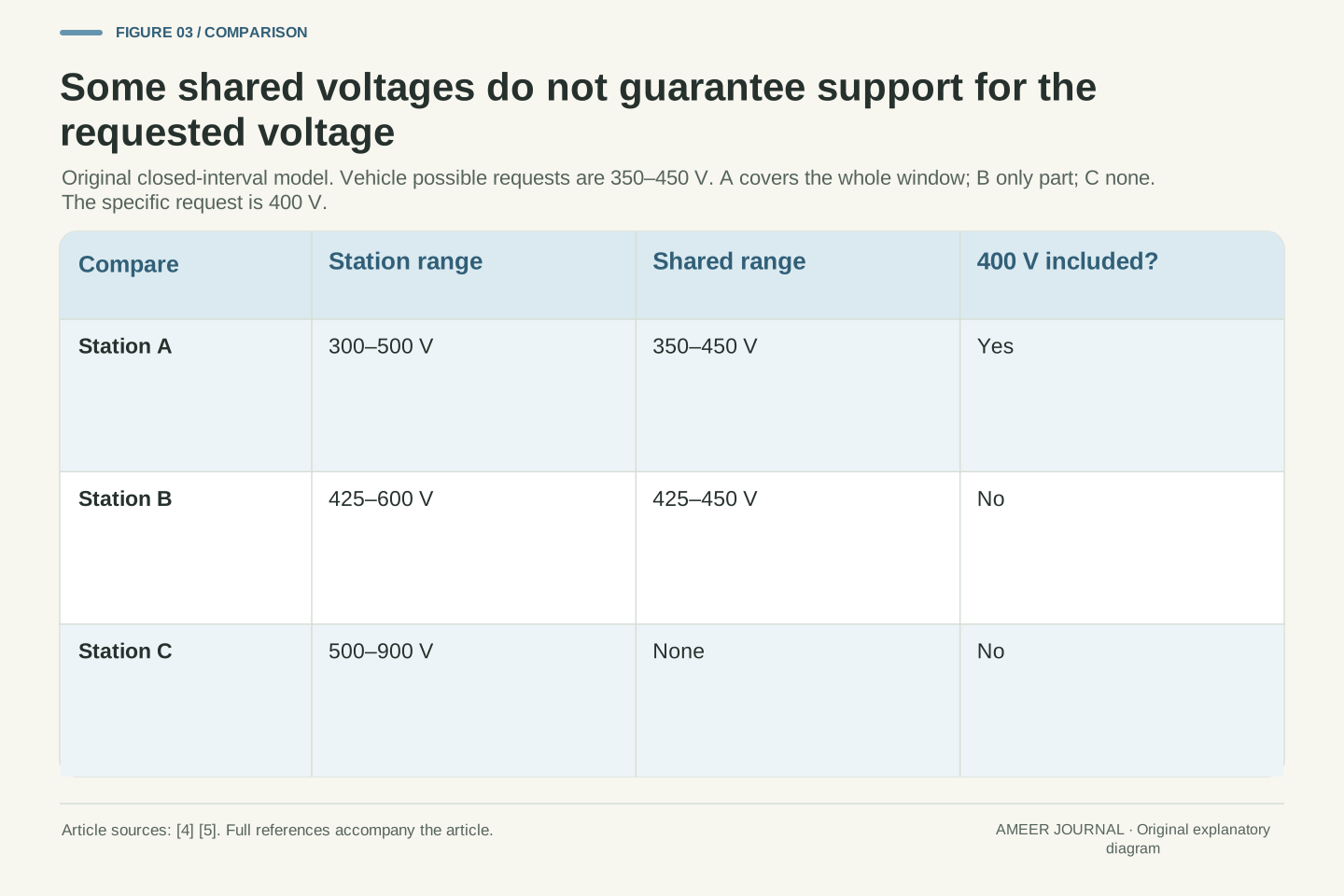
Give our fictional vehicle a possible DC-interface request range from 350 to 450 V, including both ends. Station A can supply 300–500 V, station B 425–600 V, and station C 500–900 V. These are assigned windows, not real product specifications. We are applying the voltage dependence described in the charging sources to an original comparison. [4][5] First ask whether the two windows share any values.
A overlaps the vehicle across its entire 350–450 V range. B shares only 425–450 V. C shares none. Now make the question more specific: the vehicle requests 400 V at this moment. A includes that point, but B does not, even though B and the vehicle have some overlap. A higher upper limit of 600 V has not solved B’s inability to supply the lower requested point.
The distinction is between ‘some possible request is covered’ and ‘this request is covered.’ Full-window coverage asks a third question: whether every value in the stated vehicle window is included. A passes that voltage-only test; B does not. None of these results settles the other compatibility conditions. The request is an input to the comparison, not an invitation to choose a different voltage merely to make a station’s window fit.
Let the vehicle’s possible requested interface voltages be the closed interval V=[350,450] V. Define station intervals S_A=[300,500] V, S_B=[425,600] V and S_C=[500,900] V. These invented exact ranges isolate one operating constraint motivated by voltage-dependent DC delivery. [4][5] Nonempty V∩S establishes the existence of at least one shared voltage; it does not establish that all requested voltages are supported.
The intersections are [350,450] V, [425,450] V and the empty set respectively. For the particular request U_req=400 V, membership in S_A holds, while membership in S_B and S_C fails. Whole-window coverage requires V⊆S, which holds only for A. Thus an existential overlap test, a point-membership test and a universal coverage test have different logical meanings even though they use the same interval endpoints.
Outside an admissible requested-voltage point, the forthcoming scalar power ceiling is not a successful-session prediction. Its prerequisites are absent. We do not replace the missing operating point with a voltage chosen to maximize P=UI, or equate a marketing voltage class with this interval. The intervals also say nothing about protocol compatibility, transients, precision or safety qualification; they are deliberately one part of the modeled feasibility conditions.
Convert a power cap into a current cap at the stated voltage
Continue with station A at the valid 400 V point. Assign it a 50 kW power ceiling and a 200 A current ceiling. The fictional vehicle permits at most 150 A, and the complete documented path has an assigned 120 A ceiling. That last number summarizes a condition of this paper model; it is not an adapter-selection rule. For steady DC, voltage times current gives power at the same boundary. [4]
The station’s 50 kW ceiling is 50,000 W. At 400 V it permits at most 50,000 divided by 400, or 125 A. We must now satisfy four current bounds: 200 A from the station, 150 A from the vehicle, 120 A from the path, and 125 A from the station’s power ceiling. The smallest is 120 A. At that current, 400 V times 120 A equals 48,000 W, or 48 kW.
This explains why reading only ‘50 kW station’ misses part of the answer. The path current binds first in this case. ChargePoint’s discussion also separates vehicle limits, station capability and cable current when explaining delivered DC power. [5] Our numbers make that relationship explicit, without treating the result as a guarantee that a vehicle will request the maximum permitted current.
At the established U=400 V operating point, assign station bounds I_s=200 A and P_s=50,000 W, vehicle bound I_v=150 A, and complete-path bound I_p=120 A. All are constant exact inputs at the same steady-DC boundary. DOE provides the underlying P=UI relation, while ChargePoint discusses voltage, available current and vehicle control as distinct factors. [4][5] No actual cable rating is inferred from the hypothetical path bound.
The conditional current ceiling is I_max(U)=min(I_s,I_v,I_p,P_s/U). At 400 V, P_s/U=125 A, so I_max=120 A and P_max=U I_max=48,000 W=48 kW. Using the power cap in current units makes every entry in the minimum dimensionally comparable. Equivalently, one could compare U I_s, U I_v, U I_p and P_s in watts.
The formula assumes the stated current limits are applicable at this voltage and that all unmodeled session conditions have already been met. It establishes an upper bound within those premises, not a requested setpoint or a complete qualification. Its usefulness is diagnostic in the mathematical sense: it identifies which declared constraint limits the toy operating point without pretending to identify a fault in physical equipment.
The binding limit can change across the allowed voltage window
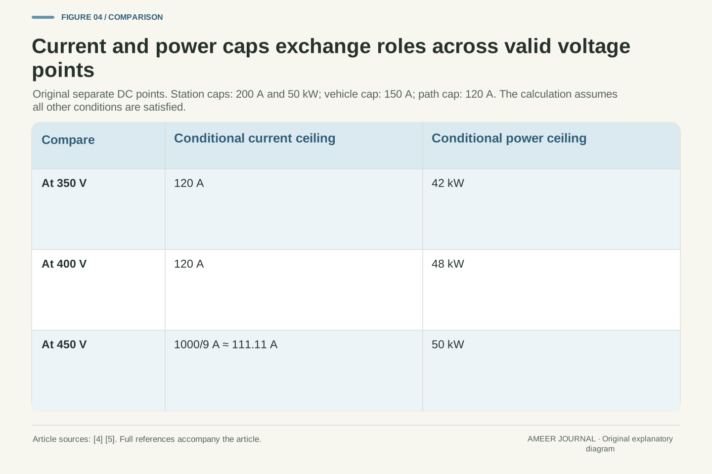
Keep every assigned limit unchanged and compare three separate valid requested voltages. At 350 V, the 120 A path ceiling allows 42 kW, below the station’s 50 kW cap. At 400 V it allows 48 kW. At 450 V, multiplying by 120 A would give 54 kW, which the station cannot provide under our assumptions. The station power ceiling now becomes the tighter condition.
To supply exactly 50 kW at 450 V, current would be 50,000 divided by 450, about 111.11 A. That is below the 120 A path limit and the other current caps. The dividing voltage is 50,000 W divided by 120 A, about 416.67 V. Below it, the path current fixes the ceiling; above it, the station power cap fixes the ceiling within the allowed window.
This is a set of possible operating-point comparisons, not a timeline of a charging session. We have not said when a vehicle would request any of those voltages, how long it would remain there, or what its battery percentage would be. The calculation explains how current and power ratings interact with voltage. It provides no basis for changing a real request to obtain a larger number.
Because I_p=120 A is below the other current ceilings, the envelope simplifies to P_max(U)=min((120 A)U,50,000 W) for admissible U in [350,450] V. The three sampled ceilings are 42, 48 and 50 kW at 350, 400 and 450 V. This is an original piecewise algebraic envelope derived from the stipulated caps and steady-DC power relation. [4][5]
The branch intersection occurs at U*=50,000 W/(120 A)=1250/3 V≈416.67 V. For U<U*, the path current is binding. For U>U*, the station power cap is binding; at U* both are active. At 450 V, I_max=50,000/450 A=1000/9 A≈111.11 A. Consequently the current ceiling decreases on the constant-power branch even though the maximum power remains fixed.
Every comparison retains its own requested voltage and the same assumed bounds. The curve is not an empirical charging curve, a time average or a battery-voltage trajectory. In particular, integrating it over voltage would not directly produce a session’s delivered energy. A time history and the realized operating path would be needed for an energy calculation; the current article establishes neither.
A permitted maximum is different from delivered power
Return to 400 V, where the conditional ceiling is 48 kW. Now stipulate a separate established session in which the vehicle requests 60 A and the station actually transfers that current. The delivered power is 400 V times 60 A, or 24 kW. This result is entirely consistent with the 48 kW ceiling. A ceiling allows lower values; it does not command the maximum value to occur.
ChargePoint describes the vehicle continuing to communicate during charging and sometimes requesting more moderate power. [5] Our 60 A example supplies no reason for that request. We have not measured temperature, state of charge or any internal decision. Several different explanations could be consistent with the same current, so the number alone cannot identify which condition selected it.
Keep three entries separate when reading a record: the declared bound, the requested value and the delivered value. In our stipulated example the request and delivery agree, but that agreement is an input, not a universal promise. Also keep power separate from energy and elapsed time. A 24 kW point, without a duration or a changing-power history, is insufficient to calculate the energy delivered over a whole stop.
At U=400 V the earlier constraints define 0≤I≤120 A. Introduce a separate realized operating point with I_req=I_delivered=60 A. Then P_delivered=400 V×60 A=24,000 W=24 kW, strictly below P_max=48 kW. Equality between requested and delivered current is explicitly stipulated for this example; the calculation does not derive controller tracking from a request message.
ChargePoint’s description of continuing vehicle control supports the distinction between available capability and the selected transfer level. [5] It does not identify the internal cause of our invented 60 A choice. A bound and an observation are different mathematical objects: the former defines admissible values, while the latter selects one point, without revealing every hidden condition that influenced it.
This distinction prevents a connector rating from becoming a session-performance claim. A single permitted or realized point establishes neither average power nor energy, and it cannot reconstruct a charging curve. A lower observed value also does not uniquely identify a cable, station or vehicle limit as active. Establishing that causal explanation would require additional state and implementation evidence beyond this scalar account.
Changing a larger rating may leave the result unchanged
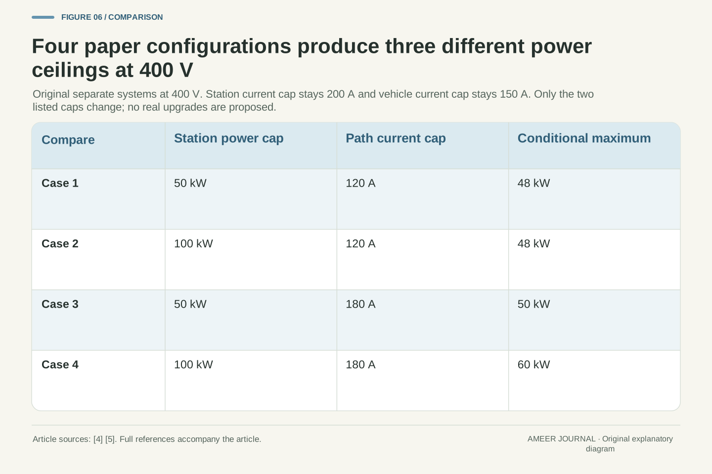
Consider four separate paper configurations at 400 V. Keep the station’s 200 A and vehicle’s 150 A current ceilings fixed. The first configuration is our original 50 kW station cap with a 120 A path cap, giving 48 kW. In the second, change only the station power cap to 100 kW. The path still permits only 120 A, so the conditional maximum remains 48 kW.
For the third configuration, use a 50 kW station cap but a 180 A path cap. The station power cap now allows only 125 A at 400 V, giving 50 kW. In the fourth, combine a 100 kW station cap with a 180 A path cap. The vehicle’s unchanged 150 A ceiling becomes the smallest bound, giving 60 kW. The four results are therefore 48, 48, 50 and 60 kW.
These are alternative assigned systems, not instructions to replace or modify equipment. The comparison answers a general reasoning question: which declared constraint is actually binding? Increasing a limit that was already above the active limit cannot change this model’s result. Relaxing an active limit may reveal another one. That is why a larger headline rating needs to be interpreted alongside the rest of the stated operating conditions.
At U=400 V, hold I_s=200 A and I_v=150 A fixed. Evaluate the four parameter pairs (P_s,I_p)=(50 kW,120 A),(100 kW,120 A),(50 kW,180 A),(100 kW,180 A). Their power-derived current bounds are respectively 125,250,125,250 A. Taking each full minimum yields currents 120,120,125,150 A and conditional powers 48,48,50,60 kW.
The second case changes a nonbinding power constraint, leaving the path-current constraint active. The third relaxes the path bound enough to make station power binding. In the fourth, both of those bounds exceed the vehicle-current bound, which becomes active. This is an original sensitivity analysis of the same minimum function, rather than four empirical equipment comparisons or a claim about the effect of a physical replacement.
The result also shows why individual rating changes cannot be assigned independent additive benefits. Raising the station cap alone adds no modeled power in the first comparison, yet it matters after the path bound is different. Constraint interaction determines the result. No compatibility condition omitted from the formula becomes satisfied merely because its scalar maximum increases; the underlying assumptions must still describe the configuration being discussed.
Read the exact adapter’s stated mode, not just the names at its ends
Return to the documented example that opened the article. Ford’s retrieved Fast Charging Adapter page describes using NACS fast-charging networks with an existing CCS1 inlet, while stating that Level 1 and Level 2 AC chargers are not compatible with that adapter. [2] The important evidence is the stated use and exclusion for that product. The example does not establish what every adapter with similarly named ends can do.
SAE’s public April 2025 adapter-report scope includes physical, electrical, functional and performance considerations and identifies the interfaces covered by that edition. [6] Reading that scope tells us why an adapter question extends beyond outer shape. It does not give us the report’s complete requirements, qualify a device, or establish a permitted vehicle-and-station combination from a photograph.
When interpreting documentation, keep the exact product, applicable vehicle, supported mode and stated conditions together. An electrical calculation can be internally correct while referring to a path that the product documentation never permits. Our interval and current examples deliberately assumed an allowed path first. They therefore cannot be used to invent an approval for an unlisted combination, even if its labels appear to fit the arithmetic.
The Ford example is a scoped counterexample to the proposition that connector-family names determine all supported charging modes. Its retrieved product description pairs NACS fast charging with an existing CCS1 inlet and explicitly excludes Level 1/2 AC applications. [2] No broader conclusions about adapter construction, conversion capability, all supported vehicles, current availability or another manufacturer’s products are warranted from that statement alone.
The public SAE J3400/1_202504 description, issued April 2025, names several classes of adapter requirements and limits that edition’s interface scope. [6] It is evidence of the report’s subject, not evidence that its full qualification process has been performed on a particular article or path. An abstract 120 A bound in this article is consequently not an OEM designation, an adapter certificate or a substitute for documented applicability.
This is a separation of proof obligations. The path’s permitted use must be established by appropriate implementation-specific documentation. Given that premise, the scalar model checks whether a requested operating point respects its assigned bounds. Success in the second exercise cannot supply missing evidence for the first. Conversely, a permitted path does not imply that every rated component reaches its headline maximum at every point.
A certificate, a description and a calculation support different claims
OCA describes formal OCPP certification for a specific implementation and protocol version, and says its test tool does not itself issue a certificate. [3] That distinction is useful even without inspecting a particular product. A label such as ‘tested,’ a statement of support and a certificate each need their own context. They should not be treated as identical evidence for every part of a charging system.
Our calculation is another kind of evidence. It proves that the invented bounds permit at most 48 kW at the specified 400 V point. It does not prove that a message exchange succeeds or that a device has passed an external test. Likewise, a station-management protocol certificate does not answer our interval-membership question: a certificate’s subject and a voltage calculation’s subject are different.
A clear comparison therefore names what was evaluated, which version or conditions applied and what conclusion followed. An older dated announcement can explain a standards milestone without establishing today’s complete device list. A product description can define an excluded use without measuring performance. These distinctions help a reader use each source for the claim it actually supports instead of treating every authoritative-looking label as a universal pass.
OCA distinguishes version-specific implementation conformance certification from simply using its compliance test tool; the tool itself does not generate a certificate. [3] This is a bounded claim about that program. It does not establish certification of any product discussed here, nor does station-management protocol conformance encompass all vehicle-facing electrical and functional questions.
The original arithmetic supplies a conditional implication: if the transfer boundary, valid voltage, current bounds, power cap and omitted prerequisites are as stipulated, then delivered power cannot exceed the computed ceiling within this model. It is not evidence that the antecedent is true for a real installation. This difference between deriving a consequence and establishing the premises is central to reading compatibility tables.
Apply the same discipline to dates and versions. The retained 2024 announcement is historical evidence; the April 2025 public report description identifies that edition’s scope. [1][6] Neither is promoted into a latest-standard claim. A meaningful record connects each assertion to the exact product, implementation or document evaluated and avoids extending a successful check beyond its stated subject.
Keep the operating point beside the compatibility claim
A useful explanation begins with the equipment and mode actually under discussion. It identifies the documented path, says which communication link a protocol claim concerns, and states the requested DC voltage before using a power rating. Those entries let a reader distinguish a missing premise from a numerical limitation. They also make the result reproducible instead of leaving ‘compatible’ to carry several unspoken meanings.
Our examples now give precise answers. Station B shares part of the vehicle’s possible voltage window but cannot supply the assigned 400 V request. Station A includes that point; under the original caps its ceiling is 48 kW. A separately stipulated 60 A transfer at the same voltage delivers 24 kW. None of these statements contradicts the others, because they answer overlap, point feasibility, maximum capability and realized transfer questions respectively.
The four alternative power-cap cases show the final benefit of keeping the conditions visible: a larger station number can leave the ceiling unchanged, or a different bound can become active. For real equipment, the applicable manufacturer and operator documentation must establish the permitted combination. This article’s contribution is an interpretation method and a worked model, with each conclusion attached to the particular evidence and assumptions that produce it.
An interpretable compatibility statement separates identity and scope from numerical operating conditions. Record the applicable hardware/implementation, supported AC or DC mode, documented path and communication endpoints before evaluating the requested DC-interface point. Then state the current and power bounds at the same boundary. This representation is not an exhaustive certification checklist; it prevents unlike pieces of evidence from being substituted for one another.
The original results illustrate the distinctions compactly. Nonempty overlap for B does not imply membership of the 400 V request. A’s voltage membership permits the subsequent conditional calculation, whose four current bounds give 48 kW. A realized 60 A point produces 24 kW without violating that ceiling. The envelope’s 42/48/50 kW samples and the separate configurations’ 48/48/50/60 kW results refer to different controlled comparisons.
No numerical result establishes the omitted premises or a time-dependent charging outcome. Nevertheless, the model adds useful precision: it identifies the quantified question, preserves the transfer boundary, determines the binding constraint and states what further evidence is needed to discuss an actual system. A physical fit, a mode description, a protocol claim and an operating-point calculation each retain their own meaning.
Sources & further reading
Explore the references behind this guide. External pages may change after our review.
- Joint Office of Energy and Transportation Continues to Advance an EV Charging Network That Works for All Consumers With Support for the Newly Released SAE J3400 EV Coupler Recommended Practice · Joint Office of Energy and TransportationJoint Office of Energy and Transportation · Accessed 7 Nov 2026
- Fast Charging Adapter (NACS) | Accessories | Ford.comFord Motor Company · Accessed 7 Nov 2026
- FAQ - Open Charge AllianceOpen Charge Alliance · Accessed 7 Nov 2026
- Electric Vehicle Supply Equipment Infrastructure – Federal Fleet Training | Department of EnergyU.S. Department of Energy · Accessed 7 Nov 2026
- How DC fast charging really works and an intro to charging curves | ChargePointChargePoint · Accessed 7 Nov 2026
- J3400/1_202504: Electric Vehicle Charging Adapter Safety and OEM-Qualified Device Designation - Information ReportSAE International · Accessed 7 Nov 2026
Article updated 7 Nov 2026.
Found something we should revisit?
Good explanations get better with thoughtful feedback.