What you’ll take away
- Heating COP compares useful thermal output with a defined electrical input; it is not a range multiplier.
- Heat taken from a source explains why useful heating can exceed the electrical input without creating energy.
- Capacity, starting thermal state and operating conditions remain essential alongside a ratio.
- Include auxiliaries and combined heating stages consistently, and calculate an interval COP from energy totals.
- Translate a heating improvement through its share of the vehicle budget before making a conditional range claim.
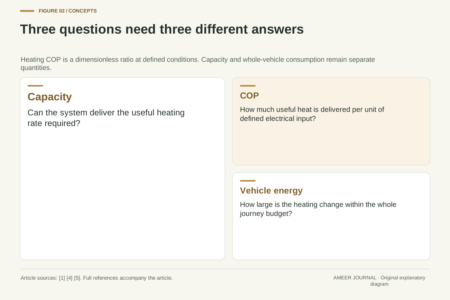
A heat-pump claim contains three different questions
An EV heat pump can reduce the electricity needed to warm the cabin by moving heat from another place. DOE describes outside air as one possible source and notes that some vehicles combine heat-pump and electric-resistance heating. [1] That tells us why the equipment can be useful, but it does not answer every question about winter performance. How much useful heat does it deliver? How much electricity does that require? How much does changing this one load affect the entire journey? A claim about the second question cannot, by itself, answer the first or the third.
The number often used for the middle question is the coefficient of performance, usually shortened to COP. For heating, it compares useful heating output with electrical input under specified conditions. [4] A COP of 2.5 is a ratio, not a distance, a temperature or a promise that the car travels 2.5 times farther. This article follows that ratio from the heating hardware to a whole-vehicle calculation. Every worked number is hypothetical. The purpose is to make a specification readable, including what its measurement leaves out, without pretending that one invented operating point describes every car or every cold journey.
Evaluate an EV heat-pump claim at three levels: heating capacity, heating-system energy performance and whole-vehicle energy consumption. DOE identifies heat transfer from outside air and the use of combined heat-pump/resistance architectures in some EVs. [1] Those are architectural facts, not a universal range multiplier. Capacity asks whether the system can deliver the required thermal power at the relevant conditions. Coefficient of performance asks how much useful heating is obtained per unit of specified electrical input. Range additionally depends on the other vehicle loads, available battery energy and the operating cycle used to turn consumption into distance.
For the heating convention used here, COP = useful heating output divided by electrical input, with identical energy or power units in numerator and denominator. ENERGY STAR's definition explicitly ties the quantities to a single set of operating conditions and treats COP as dimensionless. [4] We use that general definition, not its residential certification thresholds as EV standards. The examples below deliberately distinguish a compressor-level boundary from a complete heating-system boundary and from the vehicle battery budget. No efficiency, capacity, temperature or range value in those examples is presented as a measured production-vehicle result.
The extra heat comes from a source outside the electrical input
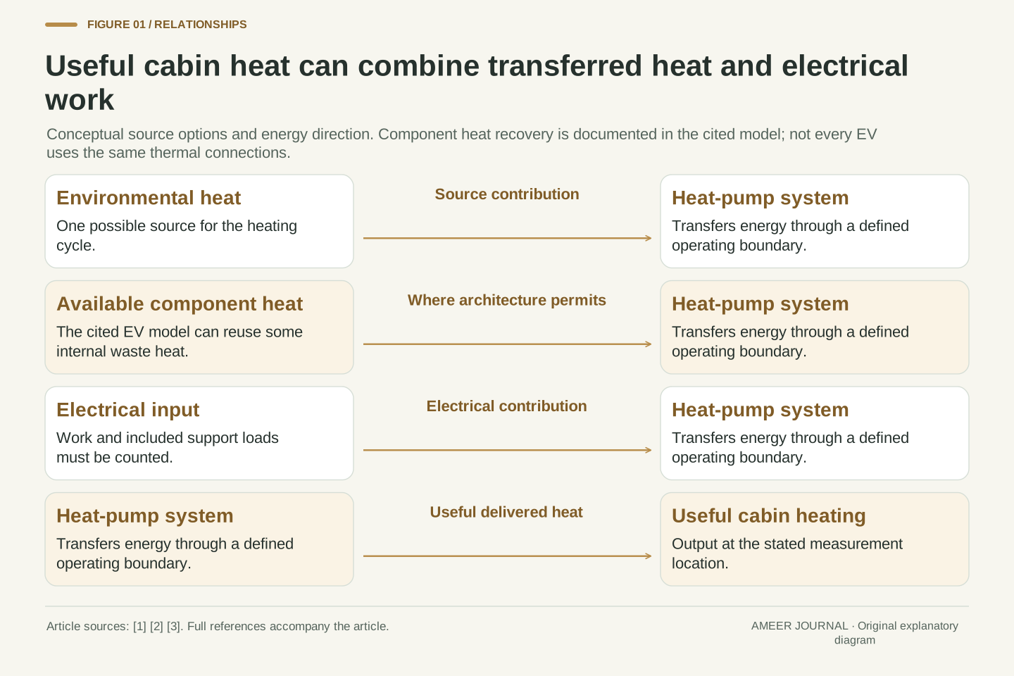
A heat pump does not turn one unit of electricity into several units of newly created energy. It uses electrical work to move thermal energy from a source toward the place being heated. The IEA describes a refrigerant circuit, a compressor and heat exchangers connecting that source and destination. [2] In heating mode, the useful heat delivered can include both energy taken from the source and the electrical energy supplied to the process. Once both inputs are counted, the apparently surprising output has an ordinary energy explanation. The source contribution is why the heating ratio can be greater than one.
A car's source and plumbing need not be identical to a household installation. MathWorks' documented EV model includes paths that can use environmental heat and some heat from the battery and power electronics. [3] That is an example of a modeled thermal architecture, not proof that every EV has those connections or uses them at the same time. It shows why a heat-pump badge does not fully describe the system. The surrounding components, valves and operating mode determine which heat is available and where it goes. A diagram of possible paths is a guide to the idea, not a service map for a particular car.
For a simplified steady operating boundary with negligible accumulation and no uncounted heat paths, energy conservation gives Q_hot = Q_source + W_in. These quantities can be energies over a common interval or corresponding steady rates. The IEA's description of source extraction, refrigerant compression and transfer to a sink supplies the physical interpretation. [2] Heating COP exceeds one when Q_source contributes positively to useful heat delivery; the ratio counts W_in in the denominator, rather than all energy entering the boundary. This is not a conversion efficiency that violates conservation. It is a performance ratio defined for the service of providing useful heating.
Thermal architecture determines what can supply Q_source. The cited MathWorks EV example contains coolant, refrigerant and cabin-air loops, and its heat-pump mode can transfer some battery and power-electronics waste heat to the refrigerant. [3] We are describing that simulation's documented topology, not inferring a universal production layout. Recovering component heat can reduce the extra electrical work needed for a thermal task, but that heat already has an origin elsewhere in the vehicle energy balance. A vehicle-wide ledger must not count it as both a new external energy source and an independent reduction in the original component loss. Boundary selection prevents that double counting.
Make the COP calculation show its units
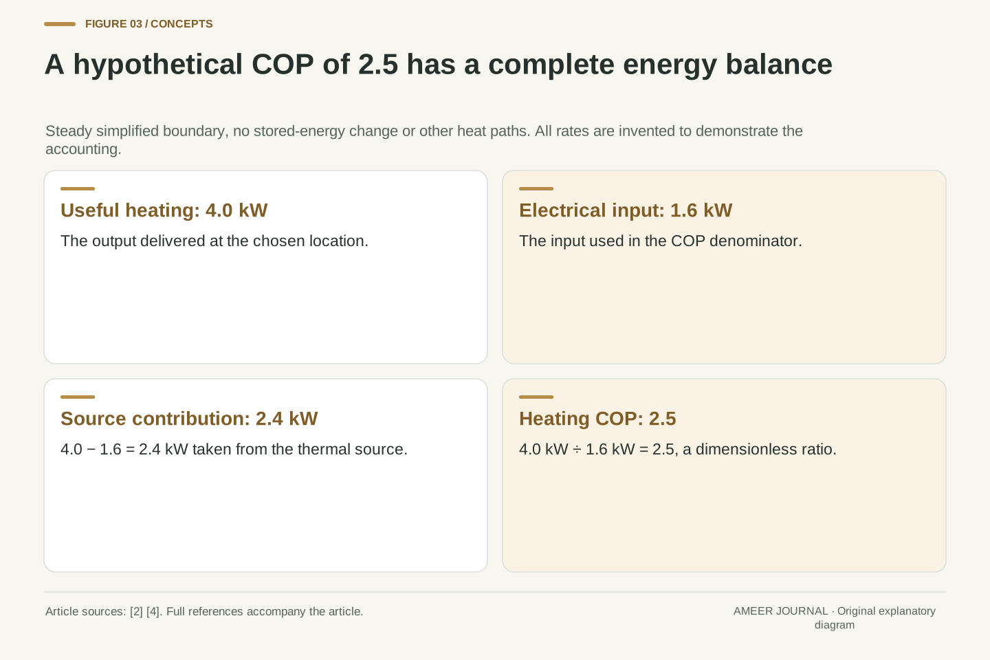
Imagine a steady heating device delivering 4.0 kW of useful heat while its defined electrical input is 1.6 kW. Its heating COP is 4.0 divided by 1.6, which equals 2.5. [4] These are invented operating values. If the simple energy boundary has no other heat paths or changing stored energy, the heat taken from the source is 4.0 minus 1.6, or 2.4 kW. The two contributions add to the useful output. That addition explains the ratio more clearly than saying the device is “250% efficient,” a phrase that often leaves the missing source energy invisible.
The same idea works with energy over time. If those rates remain steady for one hour, useful heating totals 4.0 kWh, electrical input totals 1.6 kWh and source heat totals 2.4 kWh. Divide 4.0 kWh by 1.6 kWh and the ratio is still 2.5. Do not divide a heat amount in kWh by a power reading in kW and call the result COP; that produces a time instead. The definition requires matching quantities over matching conditions. [4] A dashboard snapshot, a laboratory operating point and a full-journey total therefore need their own clearly stated time intervals before they can be compared.
Set the hypothetical useful heating rate to Q̇_hot = 4.0 kW and the chosen input rate to P_in = 1.6 kW. Then COP_h = Q̇_hot/P_in = 2.5. Under the explicitly simplified steady balance, Q̇_source = 4.0 − 1.6 = 2.4 kW. [2][4] No other energy storage or heat rejection is being hidden in this illustrative boundary. In a fuller model those terms would need to be included. The calculation shows why a large heating COP does not imply that the device produces energy: the denominator intentionally excludes the thermal energy extracted from the source.
Over a one-hour interval at these constant rates, Q_hot = 4.0 kWh, E_in = 1.6 kWh and Q_source = 2.4 kWh. Their ratio remains dimensionless because both numerator and denominator are energies in the same units. An energy divided by power would instead have units of time. ENERGY STAR's definition likewise requires compatible rates at one set of conditions. [4] For a changing operating interval, calculate total useful delivered heat and total corresponding electrical energy, rather than pairing a peak heating rate with an unrelated average input. Even when the numbers are individually correct, inconsistent intervals can manufacture a misleading ratio.
An operating point is part of the number
A COP without its conditions is incomplete. The source may be outdoor air, an available vehicle heat source, or a combination supported by the particular system. The useful destination may be cabin air, a coolant circuit or another defined outlet. MathWorks' EV model demonstrates separate thermal loads for the cabin, battery and power electronics, with different modes and controlled flow paths. [3] That example explains why “outside temperature” alone cannot describe the whole thermal state. A vehicle just starting from a cold soak and one with warmed components need not present the heating system with the same inputs or demands.
The temperature target and the amount of heat required also belong beside the ratio. A separate MathWorks vehicle model varies COP, ambient temperature and temperature targets when studying estimated range. [5] Those simulated results are not road tests, but the variable choices reveal what a simple headline leaves unresolved. A useful comparison keeps the relevant conditions visible and distinguishes a brief favourable point from a representative operating interval. We do not supply a universal temperature at which every EV switches technology, nor a fixed percentage penalty for cold weather. Those would require evidence about the actual system, controls and test conditions.
COP is a function of the operating state and of what the measurement includes; it is not an invariant label attached to a compressor. The detailed MathWorks example uses distinct cabin, battery and power-electronics loads and changes coolant/refrigerant flow paths between operating modes. [3] Its heat-recovery path can reduce the pressure difference the compressor must maintain. That specific model illustrates the role of source availability and circuit configuration. It does not establish a universal ambient-to-COP curve for production EVs, and its chosen switching temperatures should not be transferred to another vehicle's control strategy.
The separate COP-based MathWorks vehicle example explores ambient conditions and cabin/battery targets alongside thermal-system efficiency. [5] We use it as evidence of a modeling framework, not empirical validation of a particular range gain. For a test comparison, state source-side and sink-side conditions where available, starting thermal state, target comfort condition, operating mode and test duration. A warmer cabin at the end of one test can represent more useful service delivered, making a simple electricity-only comparison incomplete. Likewise, battery conditioning and cabin conditioning can draw on shared hardware without being the same useful output. Those distinctions should survive any simplification into a single reported COP.
A good ratio does not guarantee enough heat
Efficiency and capacity answer different questions. Imagine a heating demand of 4 kW. An invented unit can deliver only 2 kW at the conditions being considered, even though its COP is 3. It uses about 0.67 kW of electricity for that output, but the remaining 2 kW heating demand is still unmet. Another invented unit can deliver the required 4 kW at COP 2, using 2 kW of electricity. The first number looks better as a ratio; the second unit, under these stated assumptions, can supply the requested amount. A capacity shortfall does not disappear because the ratio is attractive.
Warm-up introduces another distinction. Heating the air is only part of changing the condition of a cold vehicle interior; surrounding materials also store thermal energy. [6] MathWorks' vehicle example explicitly represents component thermal masses and the cabin's heat transfer to its surroundings. [3] A steady operating point does not, by itself, tell you how long a cold cabin takes to become comfortable. That needs an initial state, useful output over time and the thermal loads being warmed. When comparing claims, look for both the heating capacity at the relevant condition and the time window used to describe performance, rather than treating COP as a warm-up-speed score.
Heating capacity has units of thermal power; COP is a dimensionless ratio. In a hypothetical 4 kW load case, a device limited to 2 kW useful output at COP 3 draws 2/3 kW but cannot independently meet the load. A second hypothetical device capable of 4 kW at COP 2 draws 2 kW and can meet that particular steady demand. These are not product comparisons. The calculation simply separates a feasible operating point from an efficient but insufficient one. Additional heat sources, changing load or thermal storage would need explicit treatment before claiming the first configuration achieved the same service.
Transient comfort adds stored-energy changes to the balance. [6] The detailed MathWorks thermal model represents component thermal masses and cabin heat transfer rather than reducing every thermal task to a static ratio. [3] A cold-start interval can require energy to change material temperatures as well as to offset continuing environmental losses. Consequently, equal steady-state COP does not imply equal warm-up time, and equal electricity use does not prove equal temperature trajectories. A defensible test description states the initial thermal condition and the output or comfort criterion. This article does not infer a specific transient response from the simplified steady examples or claim that a single capacity rating resolves it.
Check what the electrical-input total includes
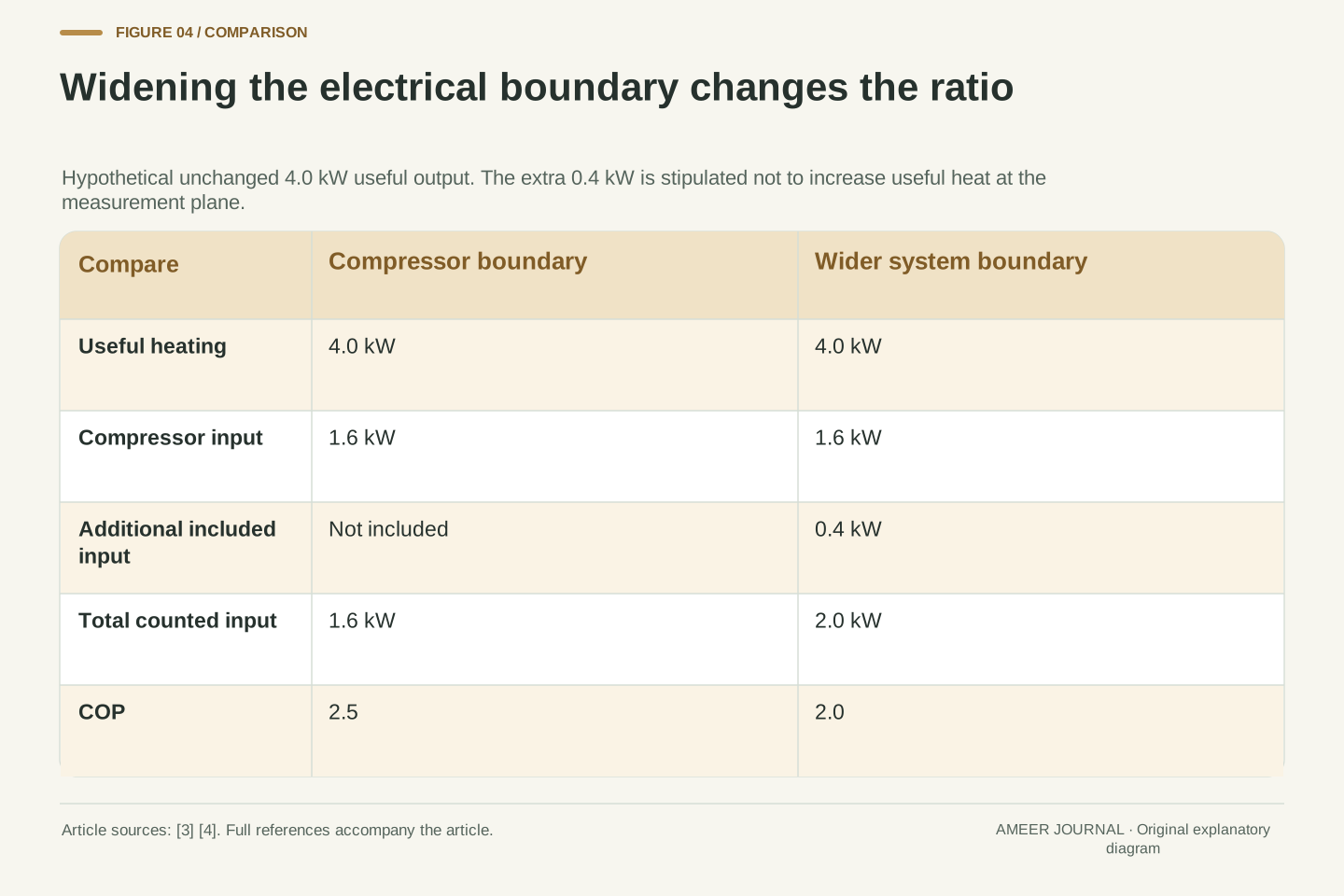
Return to the invented 4.0 kW output and 1.6 kW input. Suppose that 1.6 kW includes the compressor but excludes 0.4 kW consumed by related fans, pumps and controls. If the defined useful heating output remains 4.0 kW when we count those additional electrical loads, the wider system uses 2.0 kW and its COP is 2.0. The earlier 2.5 and the later 2.0 can both be correct descriptions of their stated boundaries. We have stipulated that the extra power does not increase the measured useful output; its energy is accounted for elsewhere, not silently turned into extra cabin heating.
The choice of boundary matters because thermal management includes more than one large component. The documented MathWorks EV example has compressor, fan, blower, pump and valve control, along with different thermal loops. [3] A compressor-only ratio should not be presented as a whole-vehicle electrical saving. Equally, a total vehicle battery draw should not be divided into cabin heat and labelled the compressor COP. Ask which loads were included, where useful heat was measured, and whether battery conditioning was part of the task. Those answers can explain a numerical difference without requiring either number to be fraudulent or physically impossible.
Let the first hypothetical boundary report Q̇_useful = 4.0 kW and compressor electrical input P_comp = 1.6 kW, giving COP_comp = 2.5. Expand the electrical boundary to include P_aux = 0.4 kW while stipulating unchanged useful delivery at the chosen measurement plane. Then COP_system = 4.0/(1.6 + 0.4) = 2.0. The auxiliary energy must leave through other accounted paths or losses in this hypothetical definition; it is not assumed to vanish. If some of it contributes to the measured useful heat, the numerator must change accordingly. The example demonstrates boundary sensitivity, not a universal auxiliary-load correction.
The detailed MathWorks EV model contains controllers for pumps, compressor, fan, blower and valves, providing a concrete reason to ask about included subsystems. [3] A report should identify whether it covers compressor input, the full HVAC system, or a broader thermal-management system serving multiple loads. Useful heating must be assigned consistently as well. Combining cabin output with only part of the electrical input inflates the reported performance; charging unrelated traction demand against a narrow heating numerator answers a different question. Clear boundaries let two test results be compared on equal terms, and prevent a component-level ratio from becoming an unsupported claim about battery energy saved.
Combined heating needs a combined calculation
DOE notes that some EVs have both heat-pump and resistance heating. [1] A mixture needs its own calculation. Imagine a heat pump providing 3 kW of useful heat at COP 3, so it draws 1 kW of electricity. Add a hypothetical resistance stage providing 1 kW of useful heat from 1 kW of electricity. Together they deliver 4 kW using 2 kW, for a combined COP of 2 before any excluded auxiliary loads. The heat-pump component still has the assumed COP of 3. It is the mixture of contributions that changes the system result.
This example also shows why merely knowing that a heat pump is fitted does not reveal which device provides all the heat during a trip. How the stages are combined depends on the system and conditions, rather than on the name of the equipment alone. [1] Do not average the component COP numbers, 3 and 1, as a general shortcut: their useful outputs and electrical inputs determine the combined ratio. In this particular example that simple average happens to equal 2, but it is a coincidence of the chosen electrical inputs. If the contributions change, the shortcut can fail while the energy-sum calculation still works.
For a hypothetical parallel contribution, assign Q̇_HP = 3 kW at COP_HP = 3, giving P_HP = 1 kW. Assign a resistance stage Q̇_R = 1 kW and P_R = 1 kW at its idealized stated boundary. The combined ratio is COP_combined = (Q̇_HP + Q̇_R)/(P_HP + P_R) = 4/2 = 2, excluding auxiliary loads not yet defined. DOE's description establishes that some EVs combine the two technologies; none of these operating numbers is taken from that source. [1] A real comparison needs the actual contributions and the useful-output boundary for both stages.
In general, combined COP is an electrical-input-weighted ratio, not an unweighted mean of component labels. Here the two electrical inputs happen to be equal, so the arithmetic mean of 3 and 1 gives the same answer. That agreement should not be generalized. With unequal input shares, sum the delivered heat and the consumed electricity directly. It is also possible for operating shares to vary through a trip, adding a time-integration problem. A manufacturer may describe combined capability without publishing the complete allocation history. In that case, acknowledge the missing information instead of assigning the heat-pump component's best COP to all heating delivered during the interval.
A heating improvement changes only part of the journey budget
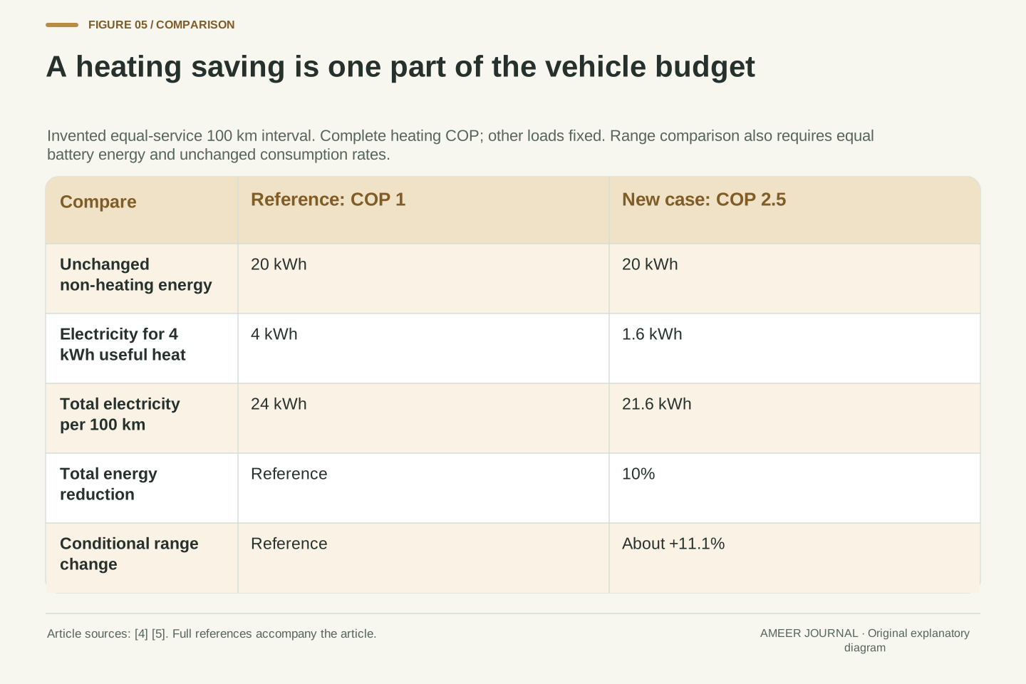
Use a new hypothetical 100 km journey with a fixed demand of 4 kWh of useful cabin heat. All unchanged non-heating loads use 20 kWh. For this example, the heating COP includes every heating-system electrical load, so nothing is added again outside it. A reference heating system at COP 1 uses 4 kWh, taking total journey electricity to 24 kWh. A system at COP 2.5 uses 4 divided by 2.5, or 1.6 kWh, taking the total to 21.6 kWh. The heating electricity fell by 60%, but total journey electricity fell by 2.4/24, or 10%.
Even that 10% energy reduction is not a 10% range increase under the corresponding fixed-energy calculation. If the same consumption rates could continue and the available battery energy stayed equal, the distance ratio would be 24 divided by 21.6, about 1.111. That is roughly 11.1% more distance in this deliberately simplified comparison. It is not a prediction for an actual car or weather condition. MathWorks' range example likewise treats thermal performance within a vehicle model containing other loads and operating assumptions. [5] The important result is the relationship: a component improvement acts through its share of the whole budget, and range is the inverse of energy used per distance.
Define a separate hypothetical 100 km interval with unchanged non-heating electricity E_other = 20 kWh and useful cabin-heating requirement Q_heat = 4 kWh. Use complete heating-system COP in this example, so no heating auxiliary is counted twice. At COP_ref = 1, E_heat,ref = 4 kWh and E_total,ref = 24 kWh. At COP_new = 2.5, E_heat,new = 1.6 kWh and E_total,new = 21.6 kWh. Thus heating electricity decreases by 60%, while the total decreases by 10%. These arithmetic assumptions deliberately hold useful service and other loads constant; they do not model different comfort levels, battery availability or transient conditions.
With equal available battery energy and unchanged energy-per-distance rates beyond the stated interval, range scales inversely with consumption: R_new/R_ref = 24/21.6 = 1.111111. The conditional range increase is therefore 11.111%, distinct from the 10% energy reduction. The hypothetical budget cannot establish a fleet average or a particular vehicle's cold-weather outcome. MathWorks' COP-based vehicle example illustrates how thermal efficiency is embedded alongside vehicle dynamics, mapped components and ambient/setpoint assumptions. [5] Its modeled results are not our inputs. The general lesson is sensitivity: the same COP change can produce different whole-vehicle benefits when useful heating demand or the unchanged energy budget differs.
A trip COP is a ratio of totals
Operating conditions can change during a journey, so a whole-interval ratio should use the whole interval's heat and electricity. For a final hypothetical example, imagine one hour delivering 4 kW of useful heat at COP 4, followed by one hour delivering the same 4 kW at COP 2. The first hour supplies 4 kWh of heat using 1 kWh of electricity. The second supplies another 4 kWh using 2 kWh. Totals are 8 kWh of heat and 3 kWh of electricity, giving an interval COP of about 2.67. The simple average of the labels, 3, is wrong for this example.
The difference appears because the two hours consume unequal amounts of electricity. A short good operating point cannot stand in for a cold start, changing demand or a mixed heating period. Keep the useful service consistent and include the electricity associated with it over the chosen duration. The general COP definition requires matching output and input conditions; our example extends the same accounting to a changing interval. [4] When a report gives only the highest COP seen, it has left the interval total unresolved. Useful evidence includes the period measured and the conditions within it, not just the most favourable number.
For time-varying operation, define COP_interval = ∫Q̇_useful dt / ∫P_electrical dt over the same interval and boundary. Consider two hypothetical one-hour segments with constant 4 kW useful heating. Segment A has COP 4, so it consumes 1 kWh while delivering 4 kWh. Segment B has COP 2, so it consumes 2 kWh while delivering 4 kWh. The aggregate is 8/3 = 2.666667. An unweighted time average of the two COP values would be 3 and would misstate that energy ratio. Equal duration is not equal electrical-input weighting.
Equivalently, weight instantaneous or segment COP by the associated electrical energy, provided the underlying output and input definitions remain consistent. The two weights here are 1/3 and 2/3, yielding 4/3 + 4/3 = 8/3. The ENERGY STAR definition's insistence on a consistent operating condition applies to an operating-point figure; the interval calculation explicitly sums changing conditions instead. [4] Do not merge those two forms of evidence without stating the change. A test that reports steady COP, transient energy and final cabin temperature supplies different information from a test that reports only a maximum ratio. None automatically predicts every route or heating schedule.
Ask for a comparable heating task
A useful heat-pump description tells you which vehicle configuration is being discussed, what useful heat was measured, which electrical loads were counted, and the conditions and duration of the test. It also supplies enough capacity information to show that the heating task was actually met. The sources here range from general physics and a residential definition to vehicle simulation examples; none is a test of your own car. [1][2][3][4][5] That distinction is part of reading evidence well. A model can clarify a relationship without proving the same numerical outcome on a road.
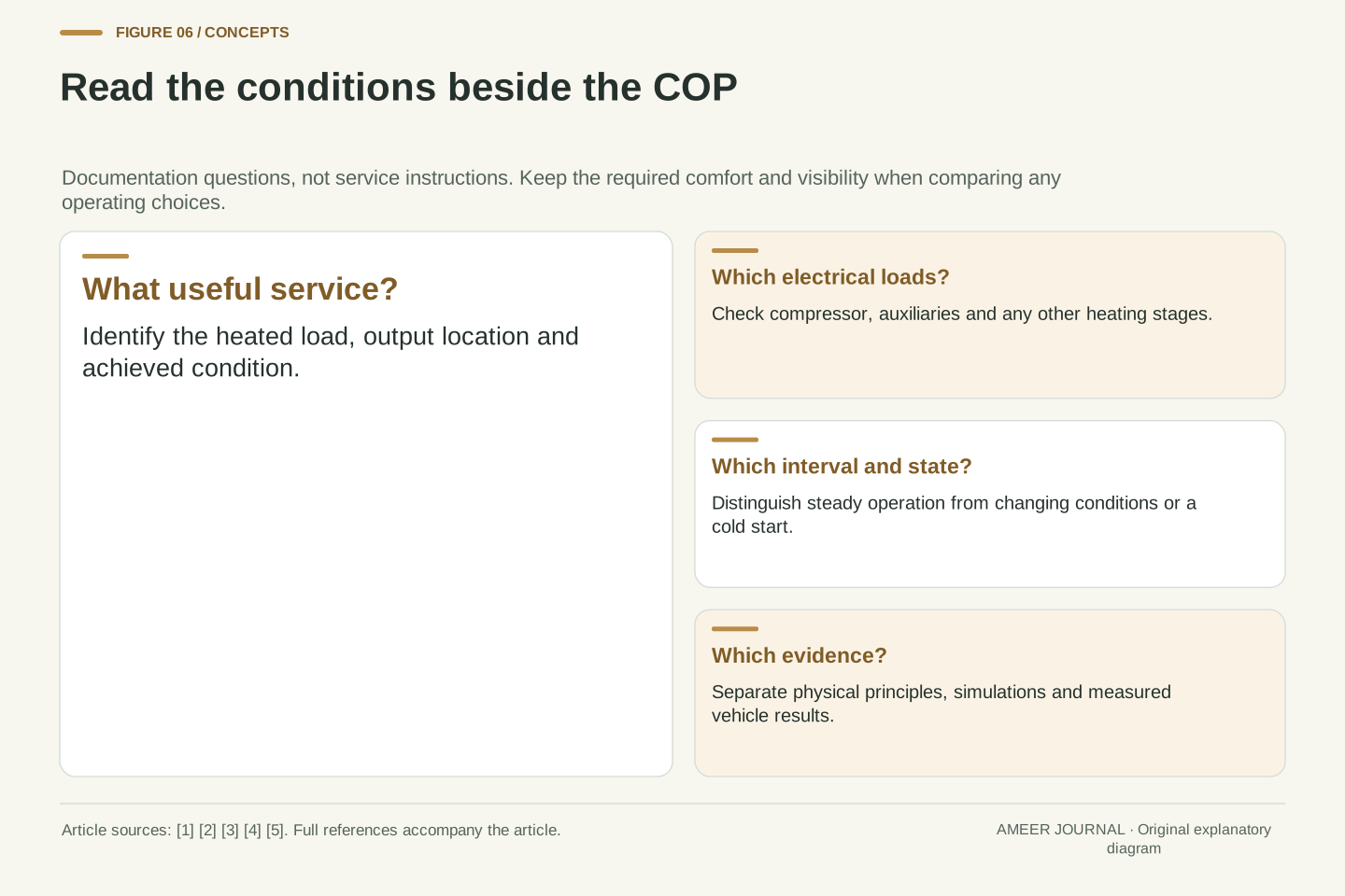
For an owner, this leads to a practical documentation check rather than a hardware experiment. Confirm the equipment and functions for the exact model and follow its operating guidance. Treat a headline COP as one part of a heating claim, and keep comfort and clear visibility as requirements rather than variables to sacrifice for a score. The strongest comparison holds useful service and conditions as consistently as possible, then shows the energy totals. With that information, a heat pump's benefit becomes understandable: a defined heating task may need less electricity, and the vehicle-level benefit follows from how much of the journey budget that task represents.
A reproducible comparison identifies the exact configuration, useful-output measurement plane, electrical boundary, source/sink conditions, initial thermal state, control mode, duration and achieved service. Capacity and transient response complement COP rather than being inferred from it. The evidence types must remain labelled: the IEA describes general operation, ENERGY STAR supplies a compatible ratio definition, DOE describes EV heating architectures, and MathWorks documents simulations. [1][2][3][4][5] This article transfers the relevant principles, not household certification thresholds or simulated performance as production specifications. If an advertisement omits those conditions, the missing variables remain uncertainties rather than values that can be filled with a generic percentage.
No refrigeration service, battery-temperature override or control modification is needed to apply this reading method. Use the vehicle's approved operating functions and preserve the required comfort and visibility. For analysis, carry useful heat, electrical input and all unchanged vehicle loads through the same clearly defined interval. Then state which result is a component ratio, which is a heating-system energy total, and which is a conditional vehicle-level calculation. That sequence explains both the value and the limits of COP. It allows a good heat pump to receive credit for the electricity it actually saves without turning its thermal ratio into an unsupported promise about driving distance.
Sources & further reading
Explore the references behind this guide. External pages may change after our review.
- Winterizing Your Electric Vehicle | Department of EnergyU.S. Department of Energy · Accessed 6 Nov 2026
- How a heat pump works - The Future of Heat Pumps - IEAInternational Energy Agency · Accessed 6 Nov 2026
- Electric Vehicle Thermal Management with Heat Pump - MATLAB & SimulinkMathWorks · Accessed 6 Nov 2026
- Heat Pump Equipment Key Product Criteria | ENERGY STARU.S. Environmental Protection Agency — ENERGY STAR · Accessed 6 Nov 2026
- Analyze Thermal Management System Effect on EV Range - MATLAB & SimulinkMathWorks · Accessed 6 Nov 2026
- Heat TransferNASA Glenn Research Center · Accessed 6 Nov 2026
Article updated 6 Nov 2026.
Found something we should revisit?
Good explanations get better with thoughtful feedback.