What you’ll take away
- Equal air-temperature drops do not establish equal heat-removal rates when moisture or flow differs.
- Humidity ratio uses dry-air mass; vapor mass fraction and relative humidity are different quantities.
- Condensate carries both mass and enthalpy through a separate outlet.
- Changing a property’s mass basis or reference must leave a consistently balanced physical result unchanged.
- A matching drain rate does not identify the complete cooling load, and heat removal alone does not establish electrical input.
Two matching temperature drops can hide different tasks
Imagine two streams of air entering a vehicle’s air-conditioning system at 30°C and leaving at 15°C. The temperature drop is fifteen degrees in both cases. It is tempting to say that the cooling task must therefore be equal. But a thermometer has not told us how much air passed through, how much water vapor it contained, or whether some of that water left as liquid. Moist-air documentation treats condensation as part of the energy account, and the documented vehicle HVAC example tracks condensation separately from air temperature. [2][4]
We will follow an original, deliberately simplified air-treatment account. One stream keeps the same amount of vapor per kilogram of dry air; the other loses some vapor as liquid. Their temperatures and dry-air flow will initially match, yet the calculated heat-removal rates will differ. Every numerical state and property coefficient is assigned for this explanation. No vehicle, sensor or software model was run. The purpose is to understand what a temperature reading leaves unresolved before treating it as a cooling-capacity or electricity-use figure.
An inlet-to-outlet dry-bulb temperature difference does not uniquely determine a moist-air heat-transfer rate. Composition and mass flow also matter, and condensation introduces a separate liquid outlet. The primary moist-air documentation identifies latent effects and constituent mass/energy balances, while the vehicle HVAC example includes both an air circuit and evaporator condensation output. [2][4] Those mechanisms motivate the calculation; they do not provide its invented parameters.
The following steady analytical construction compares two assigned air states at the same dry-air flow and temperature drop. Its constituent enthalpy laws are deliberately rounded, with an explicit reference and mass basis. They are not an implementation of EnergyPlus or Simscape, a physical coil fit or an EV performance measurement. We calculate heat removed from a specified air-treatment boundary. Compressor electricity, whole-vehicle thermal demand and battery-range consequences remain separate quantities requiring additional information.
Draw a boundary that lets the liquid leave
Our imaginary treatment box receives air, delivers cooler air and can send condensed liquid through a separate outlet. It has settled into a steady condition: no air, water or energy is accumulating inside. Dry air passes through without being created or removed. Water may stay as vapor or leave as liquid. Heat is transferred out of the box, but we exclude a fan or other machine doing work inside this boundary. The source documentation uses control volumes and explicitly accounts for the mass and energy carried away by drained condensate. [2]
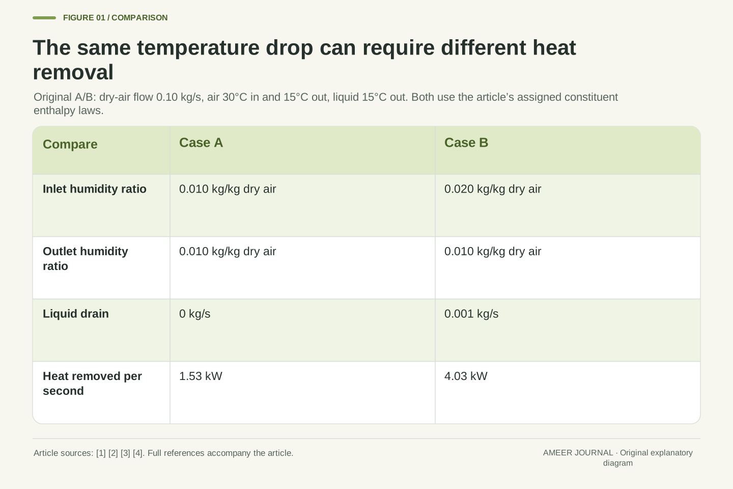
For the first two cases, the dry-air flow is 0.10 kilograms each second. Both air streams enter at 30°C and leave at 15°C. Any drained liquid also leaves at 15°C. These endpoints describe a composite air-treatment boundary, not a claim that one uniform evaporator surface produces every assigned state. We leave out changing cabin heat storage, sunlight, passengers and other vehicle loads. That limited boundary makes it possible to follow each included amount without quietly assigning unrelated cooling work to the same temperature drop.
Use a steady open control volume with one incoming gas stream, one outgoing gas stream, a liquid-water drain and outward heat transfer. There is no accumulation, shaft work, trace gas, entrained liquid in the gas outlets, or relevant kinetic/potential-energy change. The dry-air mass flow ṁ_a is conserved. Vapor and liquid together conserve water. These are selected simplifications of the documented mass/energy control-volume treatment. [2]
Set ṁ_a=0.10 kg/s, T_in=30°C and T_out=15°C for cases A and B; drain temperature is also 15°C. The boundary may encompass more than one air-treatment process, so the specified outlet is not assumed to be a saturated state at one uniform coil temperature. A real air-conditioning layout would require more detailed transport and control information. Here the task is to close the steady flow account before adding a compressor, fan or changing cabin state. Heat removal is positive outward throughout the calculation.
If liquid were accumulating inside the box, the drain would not equal the instantaneous vapor removal. The more general water balance includes a storage derivative: incoming vapor minus outgoing vapor minus drained liquid equals the rate of change of stored water mass. [2] Setting that derivative to zero is therefore a meaningful part of this steady construction, not an identity that every transient drain reading automatically satisfies.
Name what the moisture number is divided by
The humidity ratio tells us the mass of vapor accompanying a given mass of dry air. A value of 0.010 means ten grams of vapor per kilogram of dry air. A value of 0.020 means twenty grams per kilogram of dry air. EnergyPlus documents this dry-air denominator. [1] Give case A an inlet ratio of 0.010 and case B an inlet ratio of 0.020. Both leave at 0.010. Case B therefore has extra incoming water to account for, even though its temperature matches case A.
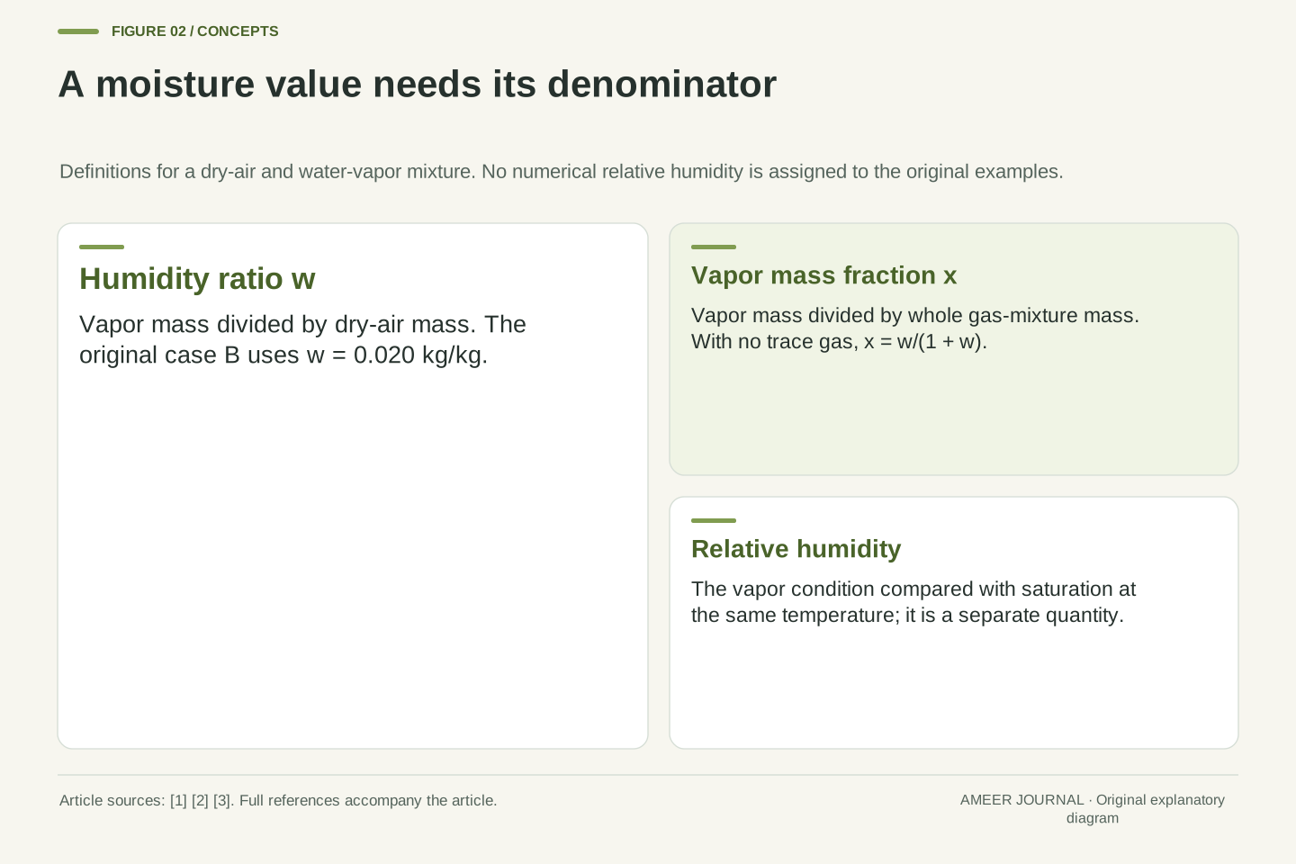
Do not read 0.020 as two percent relative humidity. Relative humidity compares the vapor condition with a saturation condition at the same temperature, while vapor mass fraction uses the mass of the whole gas mixture. [2] At our 0.020 humidity ratio, one kilogram of dry air accompanies 0.020 kilograms of vapor, making 1.020 kilograms of mixture. Its vapor mass fraction is 0.020 divided by 1.020, about 0.019608. The numbers are close but have different denominators, and neither is a supplied relative-humidity reading.
Define w=m_vapor/m_dry-air, expressed numerically in kg water per kg dry air. With no trace gas, this is the dry-air humidity ratio used in the selected definitions. [1][2] Set w_A,in=0.010, w_B,in=0.020 and w_out=0.010. At a common dry-air flow, vapor flow is ṁ_aw, and total gas flow is ṁ_a(1+w). Dry-air flow and whole-mixture flow are consequently not interchangeable.
The vapor mass fraction is x=w/(1+w). For case B, x=(1/50)/(51/50)=1/51≈0.019608, whereas w=1/50. Relative humidity instead depends on vapor partial pressure compared with saturation vapor pressure at the same temperature in the documented gas model. [2] No numerical relative humidity is inferred here. Keeping these definitions separate prevents a percentage or a kilogram-per-kilogram value from silently acquiring a different denominator when it enters an energy calculation.
At a fixed total pressure and fixed composition in the documented ideal-mixture description, the vapor partial-pressure fraction is fixed even if temperature changes. Relative humidity still involves the temperature-dependent saturation pressure. [2] Consequently, retaining the same w through case A does not assert an unchanged relative humidity. Neither the temperature drop nor a humidity percentage should be substituted directly for the water mass removed.
Close the water account before the energy account
Case B brings in 0.10 times 0.020, or 0.002 kilograms of vapor each second. The outgoing air keeps 0.10 times 0.010, or 0.001 kilograms each second. The remaining 0.001 kilograms per second leaves as liquid. That would be 3.6 kilograms over an hour if all these assigned steady conditions persisted. It is a consequence of the example’s flow and moisture difference, not a typical drain rate for an EV.
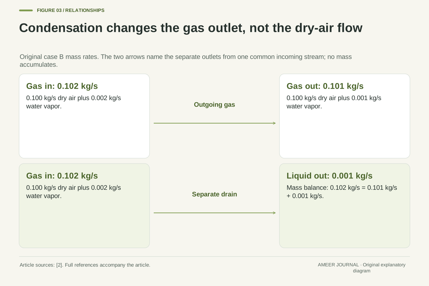
The whole-mixture mass also balances. Incoming gas contains 0.100 kilograms of dry air plus 0.002 kilograms of vapor each second: 0.102 in total. Outgoing gas contains the same 0.100 kilograms of dry air plus 0.001 kilograms of vapor: 0.101. Add the 0.001-kilogram liquid outlet and the outgoing total again becomes 0.102 kilograms per second. The gas flow has decreased because water changed outlet and phase, not because dry air disappeared. The documented condensation model likewise keeps the removed liquid’s mass in its account. [2]
Steady water conservation gives ṁ_l=ṁ_a(w_in−w_out). For B, ṁ_l=0.10(0.020−0.010)=0.001 kg/s. Incoming vapor flow is 0.002 kg/s, outgoing vapor flow is 0.001 kg/s, and the liquid carries the difference. Multiplying the assigned steady drain rate by 3600 seconds gives 3.6 kg over one hour. This is an integrated amount only under the stated constant-rate assumption.
The gas-mixture rates are ṁ_in=0.10(1.020)=0.102 kg/s and ṁ_out=0.10(1.010)=0.101 kg/s. Thus ṁ_in=ṁ_out+ṁ_l, while dry-air flow remains 0.10 kg/s at both gas ports. The distinction is central to a condensation control volume. [2] An energy calculation that uses one fixed whole-gas mass flow at both endpoints would conceal the phase-separated outlet. A dry-air normalization avoids that error only if the liquid term is still retained explicitly.
Give every flowing constituent the same reference
We need an energy account for material flowing across the boundary. The relevant property is called enthalpy. Our model assigns dry air an enthalpy of zero at 0°C and liquid water an enthalpy of zero at 0°C. Vapor at that temperature has a positive value because the reference is liquid water. The documentation explicitly distinguishes a liquid-water reference, which includes vaporization energy in the vapor value, from a vapor-zero reference. [3]
Use these rounded teaching rules: each kilogram of dry air has a value equal to its Celsius temperature in kilojoules; each kilogram of vapor has 2,500 plus twice that temperature; each kilogram of liquid has four times that temperature. For one kilogram of dry air accompanied by w kilograms of vapor, add the dry-air value to w times the vapor value. Mixture enthalpy combines constituent contributions, but the coefficients here are our stated assumptions. [2] They let the same reference follow water from the incoming vapor to the outgoing liquid.
Let t denote the numerical Celsius temperature relative to 0°C. Assign constituent specific enthalpies h_a=t kJ/kg dry air, h_v=(2500+2t) kJ/kg water and h_l=4t kJ/kg water. These rounded laws use dry air and liquid water at 0°C as their respective zero references. The vapor’s 2500-kJ/kg offset retains the phase difference. The source’s selectable liquid-water reference supports this distinction; its internal software conventions are not being reproduced. [3]
For a gas mixture normalized by dry-air mass, h(t,w)=[t+w(2500+2t)] kJ/kg dry air, where w is the numerical kg/kg ratio. This follows addition of constituent enthalpy contributions. [2] Thus h_A,in=55.6, h_B,in=81.2 and h_out=40.3 kJ/kg dry air. The 15°C liquid has h_l=60 kJ/kg water. The reference choice is arbitrary, but it must remain consistent across both water phases and every inlet/outlet term.
Specific enthalpy is not the total energy of the entire cabin. Multiplying it by the corresponding mass flow gives an energy-flow rate at a control surface. The mixture and constituent labels matter because a kilogram of dry air accompanied by vapor is more than a kilogram of whole gas. This distinction remains necessary even when the two numerical mass rates differ only slightly.
Start with cooling that removes no vapor
Case A enters with the same ten grams of vapor per kilogram of dry air that it carries out. There is no liquid drain in this case. Its inlet enthalpy is 55.6 kilojoules per kilogram of dry air, and its outlet value is 40.3. The difference is 15.3 kilojoules for each kilogram of dry air passing through. At 0.10 kilograms per second, the heat-removal rate is 1.53 kilojoules per second, or 1.53 kW.
The fifteen-degree drop alone would give 1.50 kW if we counted only our dry-air heat capacity. The remaining 0.03 kW comes from cooling the vapor that stays in the gas. No vapor has to become liquid for it to contribute to the temperature-change energy. This first case supplies a useful reference: the temperature drop, flow and remaining moisture all have explicit roles. It also shows why calling a stream dry merely because it produces no condensate would misdescribe its composition.
For A, w_in=w_out=0.010, so water conservation gives zero condensate flow. The steady heat-removal rate is Q̇_A=ṁ_a(h_in−h_out)=0.10(55.6−40.3)=1.53 kW. The equality uses kg dry air/s multiplied by kJ/kg dry air; the dry-air units cancel correctly. There is no drain-energy term because its mass flow is zero.
Under the assigned constant constituent slopes, the effective heat capacity per kilogram of dry air is 1+2w=1.02 kJ/(kg dry air·K). Consequently Q̇_A=0.10×1.02×15=1.53 kW. Its dry-air contribution is 1.50 kW and its unchanged-vapor sensible contribution is 0.03 kW. This separates composition from phase change: noncondensing moist air still carries vapor enthalpy. The result is a property of the declared mixture and coefficients, not a general assertion that 0.10 kg/s of any air stream requires this cooling rate.
The liquid carries energy through a different outlet
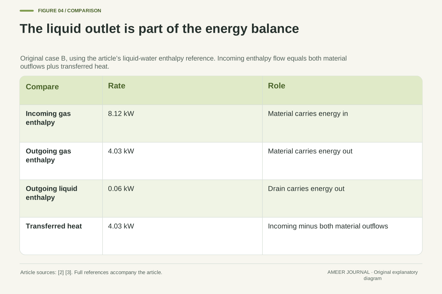
The wetter incoming stream carries 0.10 times 81.2, or 8.12 kW of enthalpy flow at our chosen reference. Outgoing air carries 0.10 times 40.3, or 4.03 kW. The drained water carries 0.001 times 60, or 0.06 kW. Subtract both outgoing material contributions from the incoming one: 8.12 minus 4.03 minus 0.06 leaves 4.03 kW transferred out as heat. The repeated 4.03 values are a numerical coincidence: one belongs to the outgoing air and the other to heat transfer.
Subtracting only the two air-stream values would give 4.09 kW. That is the reduction in gas-stream enthalpy flow, but part of it left inside the liquid. The documentation specifically retains the condensate’s mass and energy when it drains away. [2] Counting the entire 4.09 kW as heat transfer and also letting the liquid leave would fail the complete energy account. Both temperature drops remain fifteen degrees, yet case B’s heat-removal rate is 4.03 kW rather than case A’s 1.53 kW.
With the chosen outward-positive heat convention, the steady balance is Q̇=ṁ_a(h_in−h_out)−ṁ_lh_l,out. The liquid outlet has its own enthalpy reference and mass basis. [2][3] Substitution for B gives Q̇_B=0.10(81.2−40.3)−0.001(60)=4.03 kW. Equivalently, the full rate balance is 8.12=4.03+0.06+4.03 kW: incoming gas equals outgoing gas, outgoing liquid and transferred heat.
The air-only enthalpy reduction is 4.09 kW, exceeding transferred heat by 0.06 kW under this reference. Omitting a small liquid term can be an approximation in a separately specified calculation, but it is not exact equality for the present boundary. The liquid’s enthalpy value itself depends on reference; the final balanced heat rate does not. Case B and A differ by 2.50 kW despite matching dry-air flow and dry-bulb endpoints. Composition and phase accounting supply the missing information.
If the assigned rates persisted for half an hour, the transferred heat would be 0.765 kWh for A and 2.015 kWh for B, differing by 1.25 kWh. These are thermal amounts obtained from heat-transfer rates over one common duration. They are not battery withdrawals, and the inlet or outlet enthalpy-flow value alone is not the heat transferred during that interval.
Separate the extra vapor’s cooling from its phase change
Case B differs from A by an extra 0.001 kilograms of incoming water each second. Our laws give this vapor 2,560 kilojoules per kilogram at 30°C and the drained liquid 60 kilojoules per kilogram at 15°C. Their difference is 2,500 kilojoules per kilogram. Multiply by the extra water flow and it contributes 2.50 kW of additional heat removal. Adding that to A’s 1.53 kW reproduces B’s 4.03 kW.
We can divide that difference into two bookkeeping steps. Cooling the extra vapor from 30°C to 15°C changes its enthalpy by 30 kilojoules per kilogram, contributing 0.03 kW. Changing 15°C vapor into 15°C liquid changes it by another 2,470 kilojoules per kilogram, contributing 2.47 kW. Those parts add to 2.50 kW. This is an energy decomposition between the supplied endpoints, not a claim about the exact path through an evaporator. The sources distinguish sensible and vaporization-related quantities for this reason. [1][2]
Subtract A’s complete balance from B’s while holding ṁ_a, w_out and both temperatures fixed. The only extra material is Δṁ_w=0.001 kg/s entering as vapor and leaving as liquid. Thus ΔQ̇=Δṁ_w[h_v(30)−h_l(15)]=0.001(2560−60)=2.50 kW. This also directly verifies Q̇_B−Q̇_A=4.03−1.53.
Insert h_v(15)=2530 kJ/kg water as an intermediate accounting state. The extra vapor’s sensible reduction is 2560−2530=30 kJ/kg, and its phase enthalpy reduction at 15°C is 2530−60=2470 kJ/kg. Their rates are 0.03 and 2.47 kW. The 2500 coefficient at the zero-temperature reference is therefore not being substituted indiscriminately for a latent value at every temperature. EnergyPlus separates vapor, latent and sensible properties, and the moist-air source explains condensation’s thermal role. [1][2] Our decomposition remains an exact consequence of the assigned linear laws.
For arbitrary assigned w_in≥w_out under these same laws and endpoints, the balance can be rearranged as Q̇=ṁ_a[(1+2w_out)(t_in−t_out)+(w_in−w_out)(2500+2t_in−4t_out)], with the numerical units used above. The first bracketed term cools the dry air and vapor that remain in the outlet; the second accounts for water that leaves as liquid. This form makes the A/B subtraction visible directly.
Changing the mass basis should not change the answer
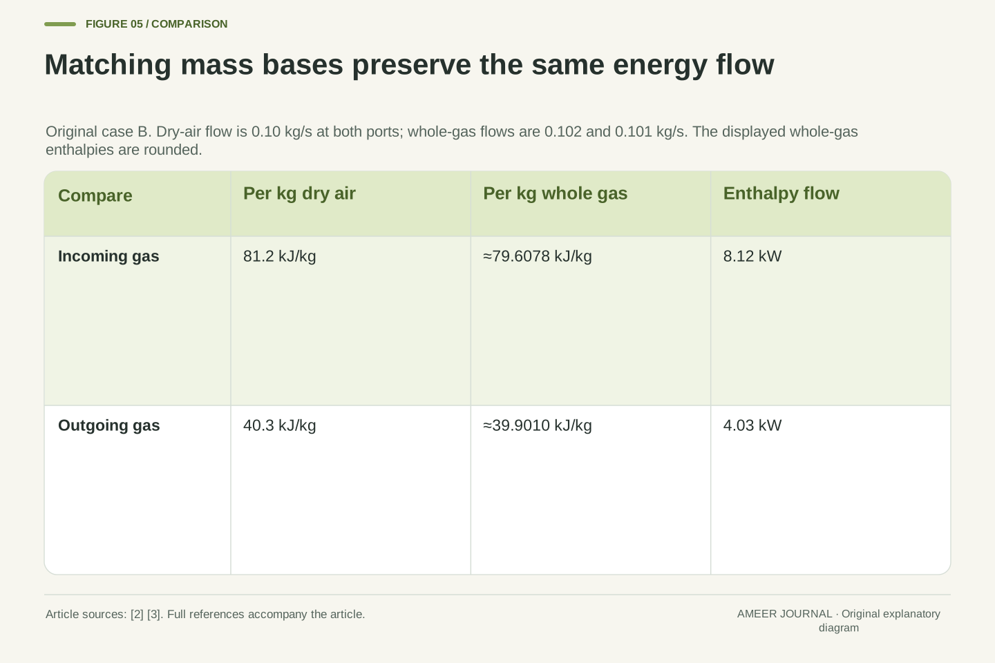
Some records report enthalpy per kilogram of dry air; others use a kilogram of the whole air mixture. The documented sensor offers those distinct normalizations. [3] Either can describe the same stream if its matching mass flow is used. For B’s inlet, divide 81.2 by 1.020 to get about 79.6078 kilojoules per kilogram of mixture. Multiplying by the actual mixture flow of 0.102 kilograms per second returns the same 8.12 kW as before.
At the outlet, 40.3 divided by 1.010 is about 39.9010 kilojoules per kilogram of mixture. Multiplying by 0.101 kilograms per second returns 4.03 kW. The liquid still carries 0.06 kW, so heat removal is unchanged. A wrong calculation would multiply whole-mixture flows by dry-air-normalized enthalpies. Doing that at both ports gives 4.1521 kW after the drain subtraction, rather than 4.03. Its inputs may all look plausible, but their denominators do not match.
For gas only, h_mix=h_da/(1+w) and ṁ_mix=ṁ_a(1+w), so ṁ_mixh_mix=ṁ_ah_da exactly. The source explicitly distinguishes these normalizations. [3] At B’s inlet, h_mix=81.2/1.02=4060/51 kJ/kg mixture; at the outlet it is 40.3/1.01=4030/101 kJ/kg mixture. Multiplication by 0.102 and 0.101 kg/s respectively gives 8.12 and 4.03 kW.
The inconsistent calculation 0.102(81.2)−0.101(40.3)−0.001(60)=4.1521 kW mixes the dry-air-specific values with whole-mixture mass flows. Its excess is 0.1221 kW. It is not simply a universal two-percent error in cooling, because the inlet and outlet factors differ. Keeping the constituent label beside kg in both mass rate and specific enthalpy exposes the mistake. A normalization change can alter the reported specific number without altering the underlying energy flow.
An equal drain rate does not establish equal cooling
Consider a separate case C with twice the dry-air flow: 0.20 kilograms per second. Its inlet humidity ratio is 0.015 and its outlet ratio is 0.010. Keep the same 30°C inlet, 15°C air outlet and 15°C liquid outlet. The moisture reduction is half as large per kilogram of dry air, but twice as much dry air passes through. The drain rate is therefore still 0.001 kilograms per second, exactly matching B.
C’s inlet enthalpy is 68.4 kilojoules per kilogram of dry air, and its outlet value remains 40.3. Its air-stream reduction is 0.20 times their 28.1 difference, or 5.62 kW. Subtract the same 0.06-kW liquid contribution to get 5.56 kW of heat removal. B and C share the temperature drop and drain rate but have different cooling rates. A visible drain, even if its amount were known, would not supply the missing dry-air flow or determine the full cooling task.
Define independent C by ṁ_a=0.20 kg/s, w_in=0.015 and w_out=0.010, with unchanged temperatures. Water conservation yields ṁ_l=0.20(0.005)=0.001 kg/s, equal to B. The original property laws give h_C,in=30+0.015(2560)=68.4 kJ/kg dry air. Hence Q̇_C=0.20(68.4−40.3)−0.001(60)=5.56 kW.
The difference Q̇_C−Q̇_B=1.53 kW occurs despite equal condensate rate and equal temperature endpoints. C is a separate assigned steady state, not a transition inferred from B. The drain identifies a product ṁ_aΔw, not each factor independently. [2] The heat account also includes the common vapor/dry-air cooling contribution, which changes with flow. This construction therefore demonstrates a limited non-uniqueness: the drain and temperature drop together do not uniquely identify heat removal without composition and flow information.
With the drain fixed at 0.001 kg/s and the same temperatures and outlet ratio, the original balance reduces to Q̇=(15.3 kJ/kg dry air)ṁ_a+2.50 kW. The variable first term explains why B and C differ: doubling ṁ_a doubles the remaining-mixture cooling contribution while the extra-water contribution stays fixed. The same drain therefore constrains only one part of the complete heat rate.
A consistent energy reference cancels out of the balance
Our values used liquid water at 0°C as the water reference. Suppose we add 100 kilojoules per kilogram to every water enthalpy, both vapor and liquid. That changes the numbers printed beside the flowing water, but it does not change the physical cooling task. B’s incoming water contribution rises by 0.20 kW. Its outgoing vapor contribution rises by 0.10 kW, and its liquid contribution rises by another 0.10 kW. The increases cancel, leaving the same 4.03-kW heat removal.
If we changed only the vapor values and forgot the liquid, the result would falsely rise by 0.10 kW. This is why a reference label belongs beside an enthalpy table, especially when phase change occurs. The source documents separate vapor-zero and liquid-zero reporting choices. [3] A consistent reference can change the individual terms without changing a correctly closed account. The cancellation is also a useful check that neither the outgoing liquid nor part of the water mass was accidentally omitted.
Shift the water reference by a constant C, applying h_v′=h_v+C and h_l′=h_l+C. Dry-air-specific gas enthalpy becomes h′=h+wC. The calculated heat-rate change is ΔQ̇_ref=ṁ_a(w_in−w_out)C−ṁ_lC=0, because the water balance gives ṁ_l=ṁ_a(w_in−w_out). This establishes reference invariance directly rather than relying on a particular zero convention. The documented reference options explain why such distinctions arise in reported properties. [3]
For C=100 kJ/kg water in B, the inlet shift is 0.20 kW, the outlet-vapor shift is 0.10 kW and the liquid shift is 0.10 kW. Their balance is zero. Shifting vapor alone would leave an artificial +0.10-kW change. The model’s original liquid-reference convention is retained for all earlier numerical results; this separate check changes only bookkeeping origins, not material states, flow rates or the selected thermodynamic laws.
Keep air treatment separate from the vehicle’s electricity account
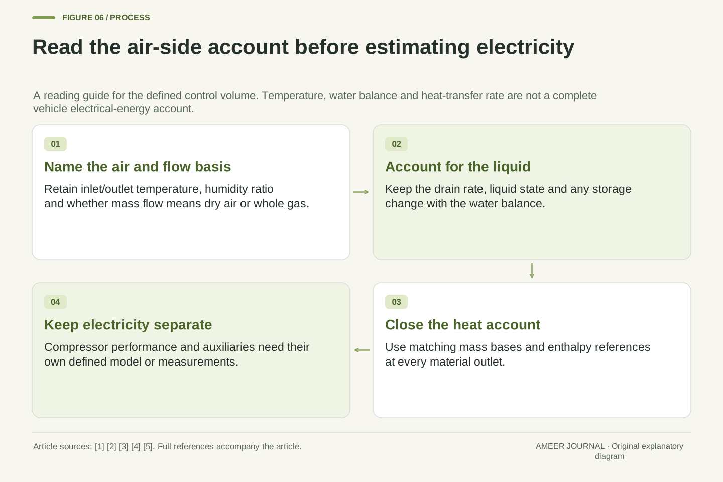
A useful air-conditioning record needs more than two temperatures. Ask what air flow was counted, whether it means dry air or whole mixture, what moisture entered and left, and whether liquid drained away or remained inside the boundary. Then check the energy reference and which outlets were included. Those questions explain the difference between our 1.53-kW and 4.03-kW tasks without assigning either to a real car. The documented vehicle model’s separate air, evaporator and condensation quantities illustrate why the labels matter. [4]
Heat removal is also not the compressor’s electrical input. Connecting the two requires a stated performance relationship and a clear account of fans, pumps and other loads. The laboratory’s vehicle research treats climate-control energy and thermal-management requirements as connected but separate parts of the wider vehicle problem. [5] None of our heat rates alone predicts battery consumption or summer range. The result you can carry forward is precise: temperature, flow, moisture, drain and boundary together define the cooling account that a temperature reading by itself cannot provide.
A reproducible steady air-side record retains inlet/outlet dry-bulb temperature, humidity ratio, dry-air or mixture mass flow with its basis, condensate state and rate, enthalpy convention and all excluded work/storage terms. The vehicle documentation provides an example with distinct cabin-air, evaporator and condensation outputs. [4] Our construction shows why retaining that separation matters before interpreting a reported capacity.
The thermal result Q̇ is not an electrical power measurement. An electrical model would need the appropriate cooling-performance ratio at the stated conditions, its included auxiliaries and its connection to other vehicle thermal services. Vehicle thermal-management research addresses those wider energy interactions. [5] No such ratio or full-vehicle energy account is supplied here. The exact conclusion is confined to the air-treatment balance: equal temperature drops, and even equal temperature drops plus equal drain rates, can coexist with different heat-removal rates when the remaining mass and composition information differs.
Sources & further reading
Explore the references behind this guide. External pages may change after our review.
- Psychrometric servicesEnergyPlus documentation · Accessed 7 Nov 2026
- Modeling Moist Air Systems - MATLAB & SimulinkMathWorks · Accessed 7 Nov 2026
- Thermodynamic Properties Sensor (MA) - Measure specific enthalpy, density, specific heat at constant pressure, and specific entropy of air mixture - MATLABMathWorks · Accessed 7 Nov 2026
- Vehicle HVAC System - MATLAB & SimulinkMathWorks · Accessed 7 Nov 2026
- Electric-Drive Vehicle Thermal Management
| Transportation and Mobility Research | NLRNational Laboratory of the Rockies · Accessed 7 Nov 2026
Article updated 7 Nov 2026.
Found something we should revisit?
Good explanations get better with thoughtful feedback.