What you’ll take away
- Compare sensor size, focal length and viewpoint separately before interpreting a tighter frame.
- With matched aspect ratios, crop factor is a linear framing ratio; area and retained pixel counts scale in two dimensions.
- Matching a field of view does not establish identical depth of field, detail or camera compatibility.
- A crop of an existing image cannot recreate the perspective of a new camera position.
- Check the actual camera manual before assuming that a RAW file retains image areas outside an in-camera crop.
Start with the picture you need
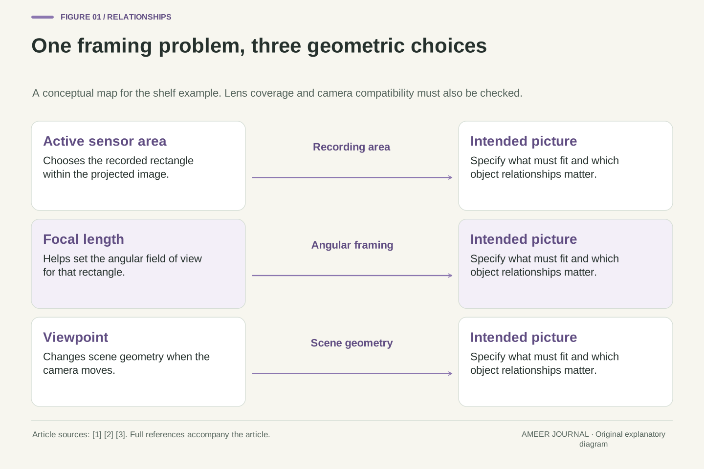
You want to photograph a display shelf, with the books at the front and a picture on the wall behind them. One camera includes the shelf edges; another seems to cut them off. Before deciding that the second camera needs replacing, ask what changed. The size of the sensor, the lens focal length and the distance from the shelf can each change how much of the scene fits in the frame. Edmund Optics treats these as connected choices in an imaging system, rather than a single camera-quality score [2].
This guide uses an imaginary shelf photograph to keep those choices separate. First, the camera stays in one position. Then we change the recording area or lens. Only afterwards do we move the viewpoint. That order makes it easier to see why a tighter frame does not automatically mean a new view of the relationships between objects. The calculations are planning examples, not measurements of a camera we tested. Nikon's description of a smaller sensor recording the central part of a lens image supplies the starting point; the practical decisions come from comparing clearly stated conditions [1].
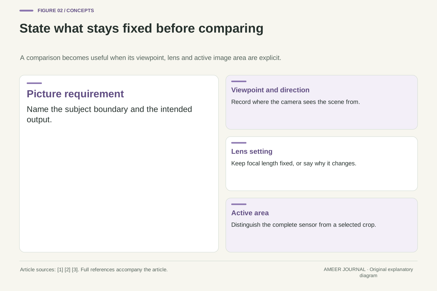
A useful format comparison starts by specifying its invariants. Are camera position and orientation fixed? Is focal length fixed? Must subject framing be matched? Is the comparison about delivered image dimensions or about the appearance of a foreground object relative to its background? Sensor dimension, focal length and working distance jointly determine field of view, so changing several of them together prevents a clean explanation of any one variable [2][3]. Define the photographic requirement before interpreting a crop-factor number.
The worked model below uses an ideal rectilinear projection, equal sensor aspect ratios, adequate lens coverage and a subject distance large relative to focal length. Numerical sensor sizes are deliberately rounded, and real lens distortion and close-focus changes are excluded. The effective viewpoint means the optical position from which the scene is seen, not an assurance that two different lens assemblies have identical geometry merely because the tripod socket stayed still. These assumptions let us isolate framing and perspective without claiming a controlled comparison of two retail cameras.
The sensor records a rectangle inside the lens image
Think of the lens as projecting an image and the sensor as the rectangle that records part of it. A smaller rectangle can record a smaller central portion of the same projected image. The objects have not grown inside the lens. More of the surrounding picture has simply been left outside the recording area. Nikon uses this explanation for its DX and FX formats, whose typical dimensions it describes as about 24 by 16 millimetres and 36 by 24 millimetres respectively [1]. Actual camera specifications should supply the dimensions for a real comparison.
There is a second question: does the lens project a usable image over the whole sensor? A lens intended for a smaller image area may leave the corners of a larger area dark or poorly covered. Teledyne's lens-selection guide explains this coverage problem [3]. Coverage and physical compatibility are separate checks. A large enough image circle does not by itself establish that a lens has the right mount, electronic support or usable focus range for a particular camera. Read the manufacturer's compatibility information before planning a purchase or fitting an unfamiliar combination.
Sensor format describes physical image-plane dimensions. With a fixed optical projection, reducing the active rectangle changes which rays contribute to the recorded frame; it does not alter the lens's stated focal length. Nikon illustrates this with DX and FX capture areas inside the projected image circle [1]. A comparison should therefore name both the physical sensor and the active recording area. A large sensor operating in a cropped mode is not using its complete physical width for that exposure.
Image-circle coverage is an additional constraint. The relevant circle must cover the intended sensor area with acceptable illumination and image quality; sufficient nominal coverage does not establish uniform sharpness. Teledyne describes the dark or blurred corners that can result when a lens intended for a smaller format is used over a larger image area [3]. Treat mount registration, mechanical clearance, control protocols and image coverage as separate compatibility questions. This article establishes no cross-brand or cross-generation lens compatibility from image-circle size alone.
Read crop factor as a field-of-view comparison
For our simplified example, compare a 36-by-24-millimetre rectangle with a 24-by-16-millimetre rectangle. Both have the same shape. The larger one is 1.5 times as wide and 1.5 times as tall. That is the familiar 1.5-times crop comparison used in Nikon's explanation [1]. It does not mean the smaller rectangle has two-thirds of the area: reducing both width and height leaves four-ninths of the larger area. That area calculation is our arithmetic, using the rounded dimensions, not a new camera specification.
The number helps translate a field of view. A 45-millimetre lens on the smaller format gives approximately the view of a 67.5-millimetre lens on the larger format, because 45 times 1.5 is 67.5. Its physical focal length remains 45 millimetres. If you want to go the other way, matching a 45-millimetre full-frame view on the smaller format, divide: 45 divided by 1.5 gives 30 millimetres [1][2]. Keep the reference format written beside the equivalent number; a number without that reference is easy to misunderstand.
When aspect ratios match, the linear crop ratio can be expressed using width, height or diagonal consistently. For the chosen 36×24 mm and 24×16 mm rectangles, each corresponding linear ratio is 1.5. Their areas are 864 and 384 square millimetres, so the area ratio is 2.25. Do not substitute the linear crop factor for an area multiplier. These are calculations on idealized dimensions, while Nikon's format guide provides the approximate real-format context [1].
Equivalent focal length describes the focal length required on a reference format for comparable angular framing. In the ideal model, a 45 mm lens paired with the smaller width corresponds to 67.5 mm on the larger width. To preserve a larger-format 45 mm view on the smaller rectangle, use 30 mm instead. This follows from preserving the ratio of sensor dimension to focal length [2]. Neither conversion establishes equal noise, equal resolved detail, identical background rendering or mount compatibility. Those outcomes require additional variables and evidence.
Work the shelf example without moving the camera
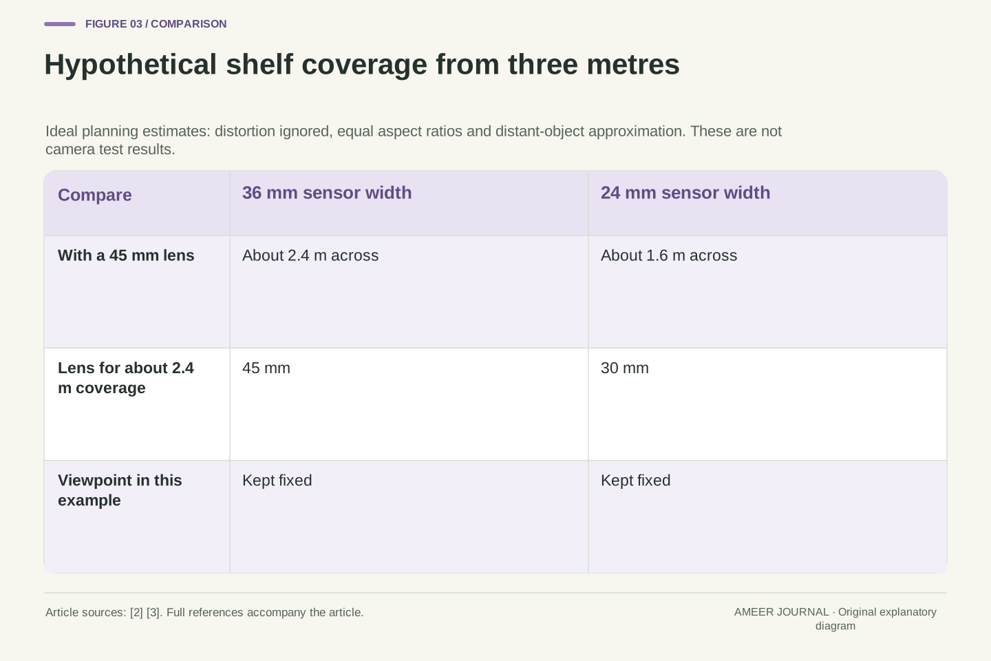
Imagine a two-metre-wide display board on a shelf, with the viewing point three metres away. We will pretend the lens has no distortion and use a rough planning calculation, not a tape-measure promise. With a 45-millimetre lens, the 36-millimetre-wide sensor covers about 2.4 metres across at that distance. The 24-millimetre-wide sensor covers about 1.6 metres. The board therefore fits in the first frame but extends beyond the second. Both pictures were taken from the same place; the smaller recording rectangle explains the difference [2].
Now keep the smaller sensor and the same viewing point, but change the hypothetical lens to 30 millimetres. The approximate width becomes 2.4 metres again. The board fits because the wider lens view compensates for the smaller sensor. The calculation is sensor width times subject distance, divided by focal length, with all three lengths in matching units [2]. Real focusing, distortion and lens geometry can change the exact result. Leave room around the intended subject, check the actual view, and use a manufacturer's lens data when precise coverage matters.
Edmund Optics gives the ideal angular relationship AFOV = 2 arctan(H / 2f), where H is the sensor dimension being compared and f is focal length. Combining the projection geometry with a distant object plane gives the planning approximation FOV ≈ H × WD / f [2]. Set WD = 3,000 mm and f = 45 mm. For H = 36 mm, the estimated horizontal FOV is 2,400 mm; for H = 24 mm, it is 1,600 mm. A hypothetical 2,000 mm board fits only the first estimate.
Preserve H/f rather than the physical focal length to match framing. The smaller format with a 30 mm lens gives 24 × 3,000 / 30 = 2,400 mm. That result is an internally consistent model comparison, not a measured image width. The approximation omits finite-focus image-distance changes, principal-plane locations and lens distortion. Teledyne specifically warns that approximating image distance by focal length becomes less reliable in close-up applications [3]. Do not use the shelf arithmetic as a macro-lens design calculation or as a guarantee of millimetre-accurate working clearance.
Moving back changes more than the border
Stepping back is another way to fit the board, but it changes where you see the scene from. To understand the difference, imagine two equally tall boxes: one is two metres from the camera and the other is four metres away. In a simple projection, the nearer box appears about twice as tall. Move the viewpoint two metres back and the distances become four and six metres; the nearer box is now about one-and-a-half times as tall. This is an original geometry example using the distance-and-magnification relationship described by Edmund Optics [2].
Cropping a picture taken from the original position cannot produce that new size relationship. It only removes parts of the existing image. Changing focal length from an unchanged effective viewpoint also keeps those ideal relative relationships, although it changes framing. Moving the camera changes the relationships themselves. In real close-up work, different lenses can have different effective viewing positions, and distortion also matters [2][3]. For an ordinary planning exercise, the useful habit is to mark where the camera is looking from before comparing tighter and wider frames.
Perspective follows the geometry between the projection viewpoint and scene points. In a simplified pinhole model, projected object height is proportional to f times object height divided by distance. The ratio for equal-height objects at 2 m and 4 m is therefore 4/2 = 2. After a 2 m backward translation, the ratio becomes 6/4 = 1.5. The focal-length factor cancels within each ratio. This is a derived illustration using the ideal projection relationships, not a claim that a manufacturer conducted this experiment [2].
Holding the effective viewpoint and orientation fixed while changing sensor crop or focal length preserves the ideal perspective relationships within the shared scene region. Repositioning the camera to restore subject size changes them. A photograph described only as having the same subject size may therefore conceal a different viewpoint. Real lens entrance-pupil locations, distortion and close-focus behavior complicate an exact comparison [2][3]. Record those limitations rather than attributing every visible difference between two photographs to sensor format.
Treat background blur as a separate decision
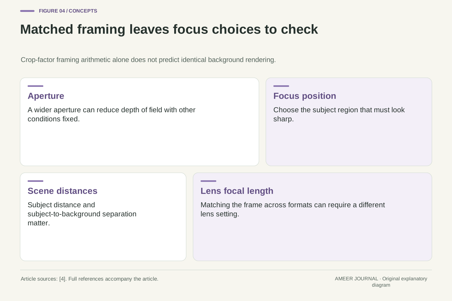
Once the board fits, you may still dislike how clear the wall behind it looks. Framing and background blur are different questions. Canon's guide discusses focal length, aperture, focus position and shooting distance when explaining depth of field, alongside the background's distance when considering its appearance [4]. Changing the lens to match framing has already changed one of those conditions. Keeping the same f-number does not establish that every other part of the photograph will look the same.
For the shelf example, decide what should look sharp: just the front book titles, or the board and nearby objects as well. Within a given setup, a wider aperture generally makes the depth of field shallower when the other conditions are unchanged; moving closer also affects it [4]. Use those relationships to plan a check on your actual camera, rather than assigning one universal blur advantage to a sensor label. This guide supplies no exact cross-format depth-of-field conversion or predicted blur measurement. A useful comparison must state the focus distance, lens and intended final display as well as the frame.
A matched angle of view does not establish matched depth of field. In our model, changing format while holding viewpoint and framing requires changing focal length. Canon identifies focal length, f-number, focusing position and scene distances as relevant depth-of-field conditions [4]. An assertion that two photographs are equivalent must specify which of these conditions are being matched and which visual criterion is being compared. A focal-length-equivalence number alone is only a framing description.
The supported local comparison is narrower: with the other conditions fixed, opening the aperture reduces depth of field, and changing shooting distance can change it as well [4]. A full cross-format equivalence calculation would additionally need a defined acceptable-sharpness criterion and output assumptions. No such numerical rule is inferred here from the crop factor alone. For the shelf photograph, state the required sharp subject range first, then verify it using the actual lens, focus placement, aperture and output size. This separates a photographic requirement from an unsupported sensor-quality ranking.
Count the pixels that remain after a crop
Physical sensor size and pixel count describe different things. Consider an imaginary image file that is 6,000 pixels wide and 4,000 pixels tall: it contains 24 million pixels. If you crop both dimensions by a factor of 1.5, the remaining image is roughly 4,000 by 2,667 pixels, or about 10.7 million pixels. Those are chosen numbers for a calculation. The crop has narrowed the view by keeping a smaller region of the file; it has not gathered another set of detail from the shelf.
A separate smaller-sensor camera might still record 24 million pixels across its own frame. That does not make it identical to cropping the larger camera's 24-million-pixel file. Nor does it prove that it resolves more useful detail: the lens and imaging conditions must support that detail. Teledyne warns that even lens megapixel ratings can hide differences in where resolution was measured and in contrast [3]. When comparing crops, write down the remaining image dimensions and inspect the same final display size before drawing conclusions from how large a detail looks on screen.
Cropping an already sampled image reduces the available sample grid. For a hypothetical 6,000×4,000 image, a linear crop factor of 1.5 retains approximately 1/1.5² of its pixels: 24/2.25 ≈ 10.7 megapixels. Rounding is necessary because pixel dimensions are integers. This is arithmetic on a chosen image, not a measured specification of the EOS R6 or any Nikon body. The linear framing factor and the two-dimensional sample-count factor must remain separate.
A physically smaller sensor with its own full-resolution capture cannot be characterized merely by applying this crop arithmetic to a different camera's file. Sampling density, optical contrast and actual camera processing are additional variables. Teledyne notes that lens megapixel labels can obscure field-dependent resolution and differences in contrast at spatial frequencies below a stated limiting resolution [3]. Consequently, equal framing and equal output pixel dimensions are useful comparison controls, but neither constitutes proof of equal recoverable detail. Avoid turning the format calculation into an unmeasured sharpness claim.
Check what your camera actually records in crop mode
A crop selected in the camera can affect the saved file differently from a crop added while editing. The Canon EOS R6 manual gives a useful specific example. It describes a 1.6-times crop setting and says that areas outside that crop are not recorded in RAW shooting. It separately explains that selecting an aspect ratio adds that information to RAW images captured at full size [5]. These are instructions for that documented camera, not a rule for every Canon body or every RAW file.
That distinction matters when you think you can fix the framing later. If the outside area was never recorded, editing cannot recover it from that file. If the camera kept the full image and only recorded a preferred shape, compatible software may give you different options. Before an important photograph, check the actual manual, file type and saved dimensions. Also keep the two crop numbers separate: the earlier shelf example deliberately used a 1.5 ratio, whereas this Canon example documents 1.6. The word APS-C does not supply one exact multiplier for every camera [1][5].
An active-area choice is part of the acquisition configuration, not merely a display preference. The EOS R6 manual distinguishes its approximately 1.6× crop from aspect-ratio selections. In the documented crop mode, outside image areas are absent from RAW capture; with an aspect-ratio selection, the manual describes full-size RAW capture with aspect-ratio information attached [5]. The distinction constrains what can be reframed later. Preserve the camera model and capture mode when using this example.
Do not infer stored sensor area from the appearance of a preview alone. Record the crop setting, file format and resulting pixel dimensions, and verify behavior against that model's documentation [5]. Likewise, do not mix a 1.5× geometrical example with a 1.6× mode and expect identical framing. Format-family names are convenient categories, while the calculation needs the actual active dimensions or a documented ratio. Lens-triggered crop selection, where supported, also belongs to model-specific compatibility information rather than a general promise about every smaller-format lens.
Build a comparison that answers one question
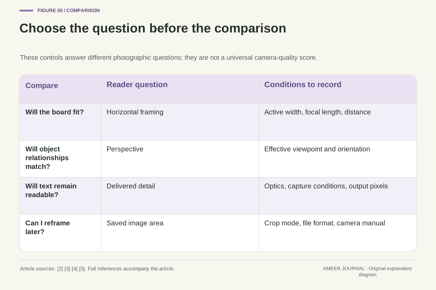
A useful comparison begins with a sentence such as: I need the whole board in the picture from this position. For that question, compare active sensor width, available focal lengths and actual image coverage. If the question instead concerns the look of the front books against the wall, keep the viewpoint clearly marked. If the question is whether small letters remain readable in a delivered image, compare the same intended output and check the lens and remaining pixels [2][3]. These are different tasks, even when the same two cameras are involved.
Write a small record beside each photograph: camera position, lens setting, active crop, aperture, focus point and exported image dimensions. You do not need to turn a family photograph into a laboratory exercise; the record simply prevents a changed condition from being forgotten. For example, a pleasingly softer wall in one image may accompany a changed lens or focus distance, both of which matter to depth of field [4]. A larger-looking word in another image may accompany a tighter crop. Describe those changes before attributing the result to sensor size.
Choose a comparison endpoint before choosing its controls. Matching angular framing requires an appropriate sensor-dimension/focal-length ratio; matching perspective requires a common effective viewpoint and orientation; comparing delivered detail requires a declared output and relevant optical conditions [2][3]. These controls are related but not interchangeable. A collection of example pictures with unknown capture geometry cannot establish which format caused a particular aesthetic or resolution difference.
For a reproducible personal comparison, log active dimensions or crop mode, nominal focal length, subject distances, aperture, focus placement and export dimensions. Keep the scene and illumination as consistent as the exercise permits, and state any remaining limitations. Canon's depth-of-field variables explain why aperture and scene distances belong in this record, while the R6 manual shows why crop and RAW behavior deserve their own entries [4][5]. This produces an interpretable observation, without presenting a casual exercise as a calibrated camera benchmark.
Try a simple observation with one camera
Place two ordinary objects at different distances on a stable indoor surface, with enough light to photograph them comfortably. Take a picture from one marked position and save the original. Make a copy and crop it more tightly. The objects should occupy more of the displayed frame, but the crop cannot reveal a different side of an object or change the size relationship already recorded between them. You are looking at a smaller part of the same picture. This follows from the recording-area idea rather than from a change to the lens [1].
Next, move to a safe second position and take a new photograph, adjusting the framing as your camera permits. Recheck focus and note every setting you changed. Compare the relative size of the near and far objects, not just the outer border. The new viewpoint can change those relationships, as the earlier geometry example predicts [2]. Treat the exercise as a way to ask better questions about your pictures. Differences in lighting, lens behavior or focus can still affect the result, so it is not a numerical test of sensor performance.
An observational exercise can isolate a digital crop from reacquisition. Preserve an original image containing foreground and background objects, then crop a duplicate without geometric transformations. Because both versions originate from the same samples, a change in the displayed border cannot introduce parallax or a new scene viewpoint. This is an implication of selecting a smaller image region, consistent with Nikon's central-area explanation [1]. Use unmodified source files so the comparison is not confounded by unrelated editing.
A second acquisition after moving the camera is a different experiment. Record the new viewpoint, refocus as required and adjust focal length only if matching the intended framing is part of the task. Compare relative object sizes while acknowledging lens distortion, finite-focus behavior and practical setup differences [2][3]. The exercise demonstrates why cropping and moving are distinct operations. It does not measure entrance-pupil location, calibrate an optical system or establish comparative sensor noise. Those would require evidence beyond these two household photographs.
Make the next change for a stated reason
If the shelf does not fit and your position must stay fixed, first check the active crop setting and whether a wider compatible lens view is available. If you can move, decide whether the changed relationship between foreground and background is acceptable. If the frame already works, sensor size may not be the question that needs solving: focus, background placement or the number of pixels left after a crop might explain the problem more directly [2][3][4]. Keep your intended photograph at the centre of the decision.
A practical note can be short: fixed viewing position; two-metre board; spare space at the sides; readable text in the final image; background allowed to soften. Then list the actual camera mode and lens you will use, and check the manual before relying on an in-camera crop [5]. That note gives you something concrete to verify. The shelf arithmetic helped choose a starting view; the real photograph decides whether the framing, sharp subject range and delivered detail meet your needs. None of those decisions needs a claim that one sensor label wins every comparison.
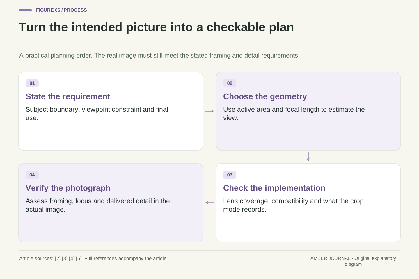
The decision sequence is requirement, geometry, implementation, verification. Specify the subject boundary and viewpoint constraint; choose a plausible active-area/focal-length combination; verify optical coverage and camera compatibility; then assess focus and delivered detail using the actual capture configuration [2][3][4]. Keep the approximation separate from the implementation. A calculated 2.4 m field of view provides a starting point, while a real lens may require adjustment to accommodate distortion, finite focus or the required composition margin.
Retain a brief record of the assumptions and the final mode, especially if crop settings affect what the file stores [5]. For the worked case, the decisive information is the desired board coverage at a constrained viewpoint, not an unsupported ranking of format names. If the geometry is satisfactory but the output fails another requirement, investigate that requirement explicitly. This preserves the useful role of sensor dimensions while preventing a framing calculation from being mistaken for a complete prediction of depth of field, recoverable detail or overall camera performance.
Sources & further reading
Explore the references behind this guide. External pages may change after our review.
- The DX and FX FormatsNikon · Accessed 6 Nov 2026
- Understanding Focal Length and Field of View | Edmund OpticsEdmund Optics · Accessed 6 Nov 2026
- Selecting a Lens for your Camera | Teledyne Vision SolutionsTeledyne Vision Solutions · Accessed 6 Nov 2026
- Depth of fieldCanon · Accessed 6 Nov 2026
- Canon : Product Manual : EOS R6 : Still Photo Cropping/Aspect RatioCanon · Accessed 6 Nov 2026
Article updated 6 Nov 2026.
Found something we should revisit?
Good explanations get better with thoughtful feedback.