What you’ll take away
- Record power source/sink separately from USB host/device roles on each connection.
- Supported USB PD role changes can leave a laptop receiving power while acting as the USB host.
- CC detection, signal routing, power contracts and display modes describe different work.
- A charging indicator does not establish that peripherals or a display path work.
- Keep old specification examples separate from current product support and observed behavior.
The charger does not have to be the USB host
A laptop receives power through the same USB-C cable that connects its keyboard and storage through a dock. At first this can sound backwards: if the dock supplies the electricity, should it also be in charge of the attached USB devices? The missing distinction is between a power role and a data role. USB Power Delivery allows the product supplying power to be either a host or a peripheral. USB-IF even gives the example of a powered monitor charging a laptop while continuing to display its picture [1]. There is no contradiction in those two jobs pointing in different directions.
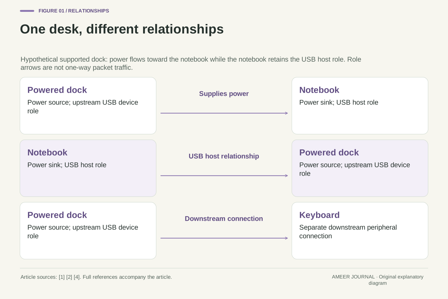
Consider an imagined desk with a notebook, a powered dock and a keyboard. Assume the manufacturers document that this exact combination supports charging and USB peripherals together. The notebook can receive power while remaining the host for the USB connection. This article follows how that arrangement becomes possible, rather than choosing cables by their advertised speeds. The useful result is a small map of who supplies power, who occupies each data role, and which part of the connection has actually been observed to work. That map makes a charging symbol much less tempting to mistake for proof that the whole desk is ready.
USB-C power direction and USB data role are distinct state variables. USB Power Delivery permits a host or peripheral to provide power, so a notebook can be a power sink while operating as the USB host. USB-IF's powered-monitor example illustrates this separation without implying that every USB-C monitor or notebook implements the arrangement [1]. The relevant unit of analysis is a particular port-to-port connection with documented capabilities, not an entire product assigned one permanent label.
Our hypothetical topology contains a notebook, an externally powered dock and a keyboard downstream of that dock. Assume ordinary USB peripheral connectivity and a supported charging connection; do not infer a particular USB4, Thunderbolt or display transport. The intended steady state has the notebook receiving power and using the dock's upstream USB connection as host. A useful explanation must account for attachment, orientation, initial roles and any required supported transition. It must also distinguish successful power delivery from successful peripheral operation. This state-based approach extends the site's cable-capability guide: it explains how apparently opposing roles coexist inside one supported connection.
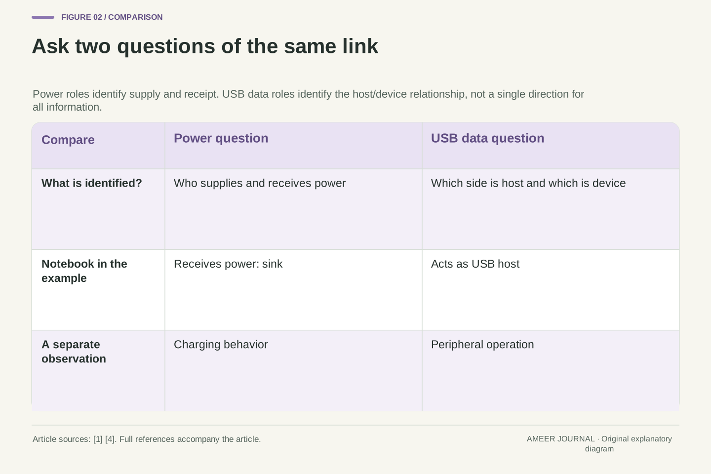
Write a power label and a data label for each end
For power, use two plain labels. A source supplies power on the connection; a sink receives it. For USB data, identify the host side and the device side. In the Type-C terminology used by the implementation documents, these are the downstream-facing port, shortened to DFP, and the upstream-facing port, shortened to UFP. The labels describe the connected port's role, not whether its case looks like a computer or accessory. Microsoft's connector documentation tracks power and data roles separately and reports changes in each [4].
Put two boxes beside each end of your imagined cable. In the notebook's boxes write power sink and USB host. In the dock's boxes write power source and upstream USB device connection. Now read each row across the cable: power has a supplier and receiver; the USB link has complementary roles. Do not draw an arrow that says all information only travels from the host toward the device. These labels identify their roles in the connection, not the only direction that useful information may travel. A keyboard supplies input to a computer even though it is not the host.
For the relationship considered here, source/sink identifies the VBUS power role, while DFP/UFP identifies the downstream- or upstream-facing USB data role. Microsoft's UCM documentation maintains data-role, power-role and negotiated-contract information separately, and exposes separate notifications for changes [4]. In our notebook-to-dock example the notebook-side DFP corresponds to the host-facing control of the USB topology; the dock's upstream port is the UFP. These descriptions are scoped to that link, because a hub also has downstream-facing connections to its own peripherals.
An analytical record should therefore contain two fields per port, not one ambiguous direction field. Write notebook=(sink, DFP) and dock-upstream=(source, UFP) for the desired state. This is a role assignment, not a physical pinout or a traffic trace. Host-to-device requests and device-to-host responses must not be collapsed into a single diagram arrow labelled data flow. Likewise, a dock's upstream power-source role does not specify the available power or data capabilities of every downstream socket. Keeping the boundary at one connector pair prevents several distinct links from being mistaken for one global dock state.
Reversibility needs detection and routing
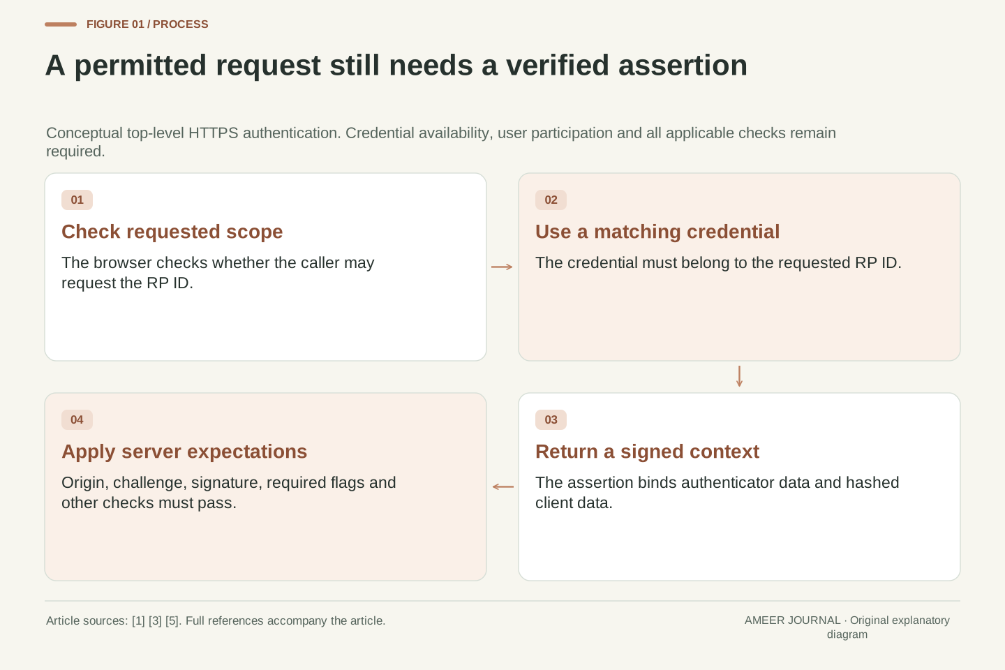
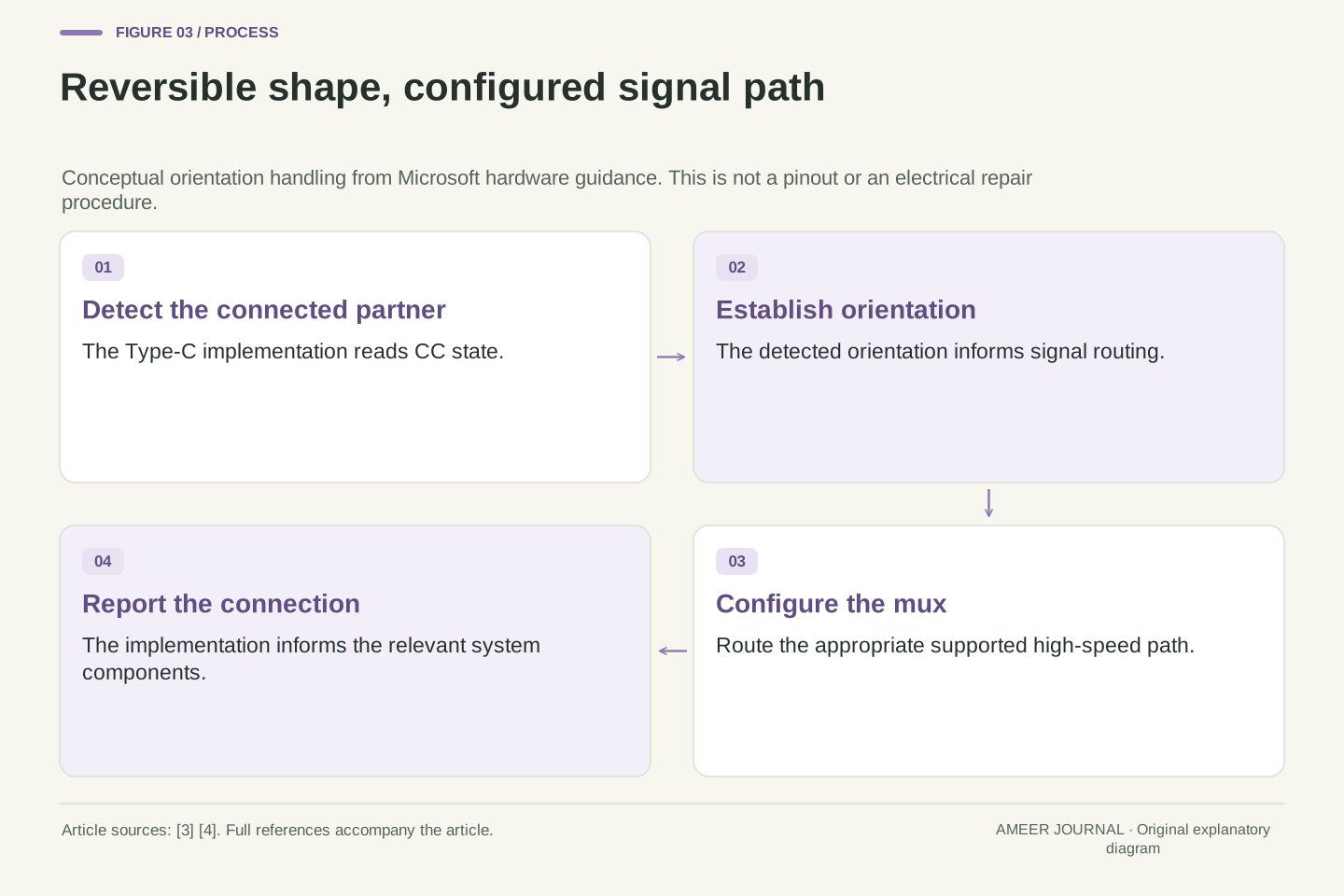
Turning a USB-C plug over does not require the person using it to choose a different role. The connection has a configuration channel, usually called CC, that helps the implementation detect its partner and the plug orientation. Microsoft's hardware overview separates the controller that handles this channel from the circuitry that routes the faster USB signal pairs. A routing switch, or multiplexer, connects the appropriate signal paths for the detected orientation [3][4]. The familiar reversible shape is backed by this electrical and control work.
Think of this as directing a visitor after identifying which entrance they used. The entrance does not become a different building, but the internal route has to match it. This is only an analogy, not a wiring diagram. It also explains why turning a plug over is not a way to command the notebook to become a charger. If a supported, undamaged connection behaves differently in the two orientations, record that difference for troubleshooting. It is an observation about the path that worked, not a diagnosis of one particular pin, a justification for modifying the cable, or proof that the software alone is responsible.
The Type-C port controller handles configuration-channel state; the system uses detected orientation to configure the signal-routing multiplexer. Microsoft's example hardware architecture explicitly separates the port/PD controller, USB controller and high-speed mux. Its connector-driver guidance requires orientation-dependent mux setup and describes reporting attachment to the USB connector manager [3][4]. Mechanical reversibility therefore should not be interpreted as all internal signal paths being permanently connected in the same way.
The practical distinction is between detecting the connection and correctly routing a supported data path. In the documented Windows implementation, incorrect mux configuration can cause a connection to operate at high speed instead of SuperSpeed [4]. This is an implementation example, not evidence that every reduced-speed connection has a mux fault. Cable capability, device capability and other conditions still require their own evidence. An orientation-dependent symptom is useful because it narrows an observation, but it does not uniquely identify a failed component. This article deliberately provides no pin-probing, resistor modification or unsupported adapter instructions; ordinary manufacturer-supported comparison is enough to preserve the diagnostic information.
The starting state can differ from the useful final state
When the connection begins, the initial power and data roles are linked in the conventional arrangement described by Microsoft's Type-C guidance: the initial source is the downstream-facing side, and the initial sink is the upstream-facing side. That is not the only arrangement compatible equipment can reach. USB Power Delivery provides separate ways to change the data role and the power role, which is how charging while acting as USB host becomes possible in its documented docking example [2].
Imagine arriving at a meeting before the seating has been rearranged. The starting positions tell you what happened first, not necessarily where everyone must stay. The important qualification is that the connected products must support the requested change. Nothing here promises that every notebook, phone or dock can switch every role. A product can have fixed capabilities, and the manufacturer's support statement matters. If a device offers no documented charging-host arrangement, the presence of two matching USB-C sockets is not enough to create one. Treat the desired final state as a requirement to verify, not a setting that must exist somewhere.
Microsoft's Windows 10-era docking FAQ describes the initial DFP as source and initial UFP as sink, followed by independent USB PD role changes where supported. It identifies a data-role swap, DR_Swap, and a power-role swap, PR_Swap, as distinct operations in that implementation [2]. The current conceptual lesson is the separation of the two state variables. The document's references to Windows 10 Mobile and Type-C specification 1.1 are historical implementation context, not a claim about the present support matrix of all platforms.
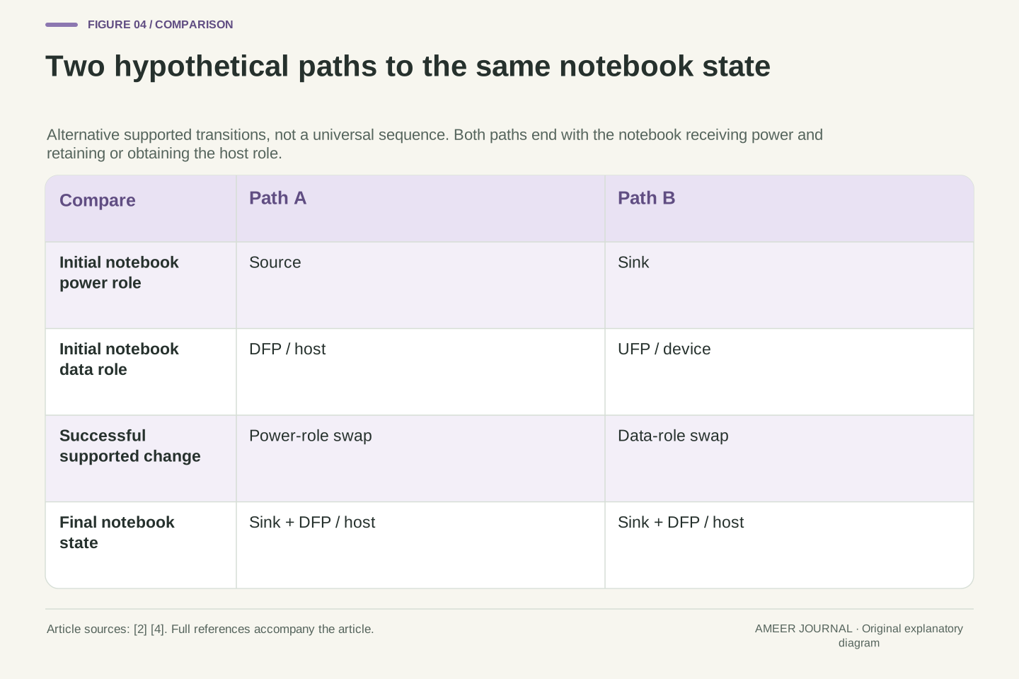
A transition should be specified by its precondition and desired postcondition. Starting notebook=(source, DFP), a supported power-role transition can yield notebook=(sink, DFP). Starting notebook=(sink, UFP), a supported data-role transition can yield notebook=(sink, DFP). These are alternative explanatory paths, not a required sequence of two swaps. They also do not guarantee acceptance: Microsoft documents reporting whether a requested operation completed successfully or unsuccessfully [4]. Device capabilities, firmware policy and the actual partner determine the supported behavior. Reading the final role pair is more useful than assuming that plugging in always causes a particular request to succeed.
A power agreement is separate from an available data path
A USB PD connection can negotiate a power agreement, often called a contract. That agreement describes the supported power arrangement between the two partners; it does not certify that a keyboard, storage device or monitor is working. Microsoft's connector documentation treats negotiated contract changes separately from changes in the USB data role [4]. USB-IF also describes power management that lets equipment take the power required by its application [1]. A large rating on a supply is therefore different from the power a particular connected product is actually using.
For a clearly hypothetical example, suppose compatible equipment agrees on an arrangement permitting 20 volts and up to 3 amperes. Multiplying those values gives a 60-watt electrical limit for that example: 20 × 3 = 60. It is not a measurement of this desk, battery charging power or an assurance of continuous consumption at the limit. Nor does the calculation contain a data speed. The useful habit is to keep three notes separate: the documented capability, the negotiated arrangement if the system exposes it, and the observed task. None should silently stand in for the other two.
A PD contract belongs to power negotiation. Microsoft's UCM implementation records advertised source capabilities and the currently negotiated contract separately, and reports changes after attachment [4]. USB-IF's overview describes flexible power direction and application-dependent power management [1]. These mechanisms do not turn the supply's largest printed wattage into a sustained load measurement, and they do not establish that the peripheral path has enumerated or that an alternate mode is available.
Use an explicitly hypothetical fixed-voltage agreement of 20 V with a 3 A current allowance. Its corresponding bound is P=VI=60 W at the stated electrical boundary. Actual current can be lower, and the example says nothing about conversion losses, system consumption, battery charge acceptance or connector temperature. It also supplies no bandwidth estimate. In a support record, distinguish advertised capabilities, selected contract and measured behavior, identifying whether the operating system actually exposes each field. If it does not expose the contract, record it as unknown instead of reverse-engineering a confident value from a charging icon or a product's marketing headline.
Work through the dock example one link at a time
Return to the imagined desk. Its intended notebook-to-dock arrangement has the dock supplying power and the notebook acting as USB host. One possible starting arrangement has the notebook already acting as host while also supplying power. A supported power-role change can then reverse the power relationship without changing the host. Another possible starting arrangement has the notebook receiving power but occupying the device-side data role. A supported data-role change can instead give it the host role while leaving the power direction alone [2][4].
Write this as two separate before-and-after stories, not a list that every connection must follow. In the first story only the power label changes; in the second only the data label changes. The desired final labels match. This little exercise is the main worked example: it explains why the end result cannot tell you which path happened at attachment. It also leaves the keyboard's own downstream connection separate. A successful keyboard response and a notebook charging indicator are useful acceptance observations for this desk, but neither observation reconstructs every message exchanged between the dock and notebook.
Represent the target notebook port as (sink, DFP) and the dock's upstream port as (source, UFP). Under the first hypothetical initial condition, notebook=(source, DFP) and dock=(sink, UFP). A successful supported PR_Swap changes the power-role components while preserving the data-role components. Under the second initial condition, notebook=(sink, UFP) and dock=(source, DFP). A successful supported DR_Swap changes the data-role components while preserving the power-role components. Microsoft's docking FAQ and separate role-change reporting support these distinctions [2][4].
Both paths end at the same target state; they are alternatives rather than a prescribed transaction trace. The exercise assumes compatible hardware and accepted requests, so it must not be used as an interoperability result. Keep the dock's downstream keyboard link outside this two-port state table. It has its own attachment and role relationship, even though the notebook ultimately uses the keyboard. For a real acceptance check, record the observed charging state and successful peripheral operation alongside the documented topology. These observations can establish that the intended tasks work in the recorded conditions, without proving every hidden state transition or performance limit.
Display support is another agreement, not another power role
A picture on a connected monitor adds a different question. The system may need to configure a supported display path as well as power and USB peripherals. Microsoft's hardware guidance describes routing signal pairs toward the display hardware when entering an alternate mode, and its connector-driver guidance assigns mode negotiation and routing work to the implementation [3][4]. That is separate work from simply being a power source or sink. The existence of a negotiated charging arrangement does not prove that the required display path exists.
In your desk notes, give the monitor its own line: exact computer port, dock, cable, monitor input and documented mode. Do not assume that a charging notebook must be able to send video through the same connection, or that a working display establishes all the dock's storage capabilities. A USB-C monitor may combine several supported functions, but the word monitor does not say which functions a particular port implements. Keeping the display question separate also avoids assigning every modern dock to one transport; USB4, Thunderbolt and alternate-mode designs need their own specific documentation.
The data/power role pair is necessary context but does not fully describe alternate-mode configuration. In Microsoft's example architecture, muxing can route high-speed pairs and possibly sideband signals to another functional block when entering a supported alternate mode. The connector implementation advertises, negotiates and configures that mode [3][4]. A successful power contract is therefore not sufficient evidence for a particular display transport, lane assignment, resolution or refresh rate.
Treat video as an additional documented path through the topology. This article does not identify every dock as DisplayPort Alternate Mode, or infer USB4/Thunderbolt tunnelling from its connector. Those architectures require their own capabilities and operating constraints. For the hypothetical notebook desk, annotate the intended monitor input and supported host/dock mode separately from notebook=(sink, DFP). The annotation makes an unresolved display requirement visible without disturbing the already understood charging-host relationship. If the image is absent while ordinary USB peripherals work, investigate the documented display path rather than concluding that the notebook must have the wrong power role.
Keep old implementation guidance inside its boundary
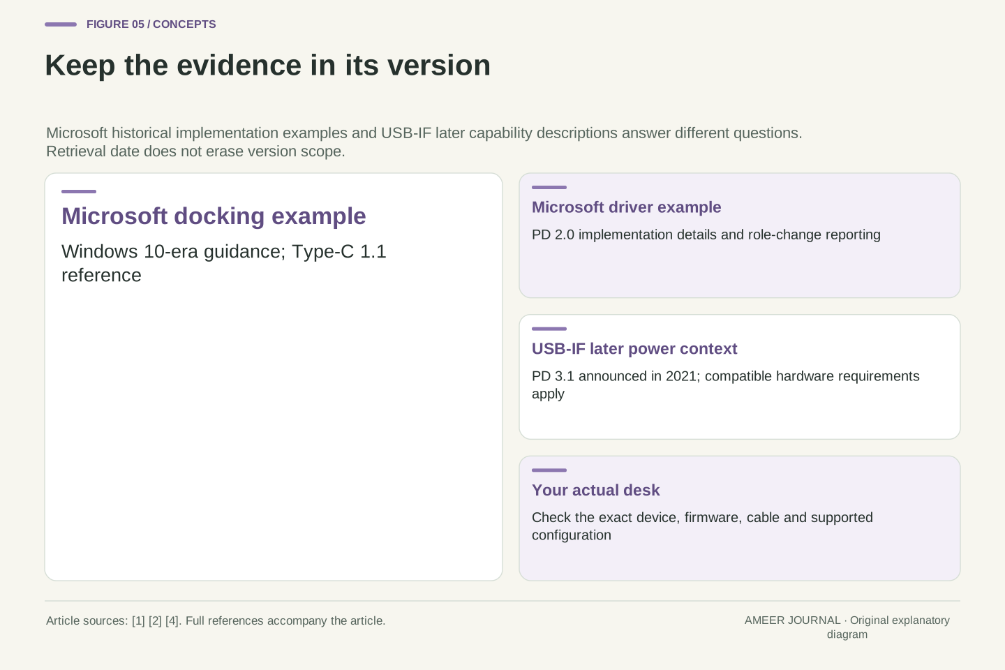
Some useful primary documents are older than the products you use today. Microsoft's FAQ explicitly discusses Windows 10 and Windows 10 Mobile, and includes a 100-watt PD description. USB-IF's later overview identifies USB PD Revision 3.1, announced in 2021, as adding capability up to 240 watts with the corresponding cable and connector requirements [1][2]. Those statements belong to different specification contexts. It would be misleading to turn the older number into a current universal USB-C ceiling.
The same care applies to software behavior. The Microsoft documents explain a particular division of work between controllers, firmware and Windows drivers. They help demonstrate that several components cooperate; they do not establish that today's notebook exposes a particular diagnostic screen or supports every described role switch. For your own setup, add the actual operating-system release, computer model, dock model and relevant firmware notes. Use the older documents for the mechanisms they explain and the current product documentation for the support decision you must make. A document's recent retrieval date does not make every example inside it new.
The evidence contains a deliberate version boundary. Microsoft's FAQ references Windows 10/Mobile and a Type-C 1.1 docking case; its driver article discusses PD 2.0 implementation interfaces. USB-IF's overview identifies PD 3.1 and Type-C 2.1 in connection with the later 240 W capability [1][2][4]. We use the older material to explain independent role transitions and the separation of controller responsibilities, not to provide a current normative power-limit table or platform-compatibility claim.
A reproducible support description should distinguish three dates: specification revision, product/firmware documentation version and observation date. Retrieving a page now verifies what the page currently serves, not that a historical operating-system example has become a current recommendation. Avoid treating API names in an older driver article as a universal repair recipe. The relevant present-day facts must come from the particular manufacturer's supported configuration. The conceptual model remains useful precisely because its boundary is explicit: power role, USB data role, negotiated contract and selected mode are separate things to establish, whatever the current product calls its user-facing controls.
Record a failure without assigning an unproved cause
A useful fault report says what happened, not what you guessed had broken. For an imagined dock that charges the notebook but does not reveal its keyboard, record those two outcomes separately. For a connection that works only with one plug orientation, record which cable end was changed and which tasks changed. Microsoft's guidance itself distinguishes charging messages, unsupported modes and role or routing behavior [2][4]. These are reasons to keep the observations separate, not permission to diagnose every failure from one icon.
Compare only ordinary, manufacturer-supported arrangements, using compatible equipment whose condition is known. Start with the smallest connection needed to observe the problem, then restore the intended desk one item at a time. Keep the exact port and cable identity in the notes; two similar-looking sockets are not evidence of identical capabilities. If equipment appears damaged or behaves abnormally, stop using that arrangement and follow the maker's support process. The goal is a clearer support question, such as charging succeeds but this documented peripheral connection does not, without opening hardware or inventing an electrical workaround.
Partition the symptom record into attachment/connection indication, available charging information, USB peripheral behavior and display behavior. Microsoft's implementation guidance presents these as related but distinguishable events and responsibilities, including role-change completion and negotiated-contract reporting [2][4]. An observed failure in one partition does not uniquely localize the cause. For example, successful power delivery is compatible with an unsupported, misconfigured or otherwise unsuccessful data path; the observation alone does not choose between those explanations.
A controlled comparison changes one documented variable while preserving the rest of the topology. Record product and port identifiers, cable identity, software/firmware versions, connected peripherals and the actual task outcome. An orientation comparison is informative only when the moved end and resulting behavior are specified. Do not infer a failed contact, controller or firmware component without additional evidence. These are proposed observation practices, not tests performed for this article. They support a manufacturer's investigation while avoiding unsupported pin-level advice, forced role changes or a false claim that a generic replacement cable must solve the issue.
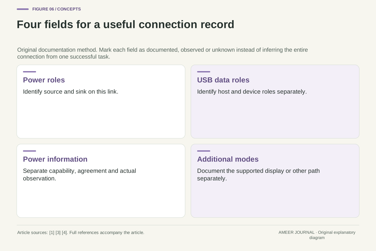
A useful connection record has four separate answers
Finish the imagined desk record with four answers. The dock supplies power to the notebook. The notebook occupies the USB host role on their connection. The accepted charging arrangement must fit both products' documented support. Any display function needs its own supported path. Those answers can coexist because USB PD permits flexible power direction and the implementation keeps role, contract and mode handling distinct [1][3][4]. A photograph of the connector cannot replace that information.
For a real desk, mark each answer documented, observed or still unknown. A manufacturer's statement is documentation; successfully using the intended keyboard is an observation; an unexposed power contract may remain unknown. Keep those categories honest when asking support for help or replacing a component. You do not need to capture protocol traffic to understand why a laptop can charge while remaining host. You need to avoid compressing several different relationships into the vague statement that the cable works. The resulting record is short enough to maintain and specific enough to survive a later dock or notebook change.
The resulting connection description has four independent fields: power roles, USB data roles, negotiated power information and any selected additional mode. The documents support treating those fields separately, with implementation-specific control and reporting [1][3][4]. For the worked topology the target pair is notebook=(sink, DFP), dock-upstream=(source, UFP), while the keyboard and any display retain their own path descriptions. The state model explains a supported outcome without asserting that one universal attachment trace produces it.
Add an evidence type to each field: manufacturer-documented capability, directly observed task result or unavailable information. This prevents a nominal rating from becoming a measurement and prevents a successful task from proving unsupported capabilities. Revisit the record when the exact port, dock, cable or firmware changes. A useful handoff contains the desired state, the observations and the remaining uncertainty, not an invented diagnosis. The practical understanding is durable: receiving power does not force a computer into the USB device role, and being the USB host does not prove that it supplies the connection's power.
Sources & further reading
Explore the references behind this guide. External pages may change after our review.
- USB Charger (USB Power Delivery) | USB-IFUSB Implementers Forum · Accessed 6 Nov 2026
- FAQ - USB Type-C connector on a Windows system - Windows drivers | Microsoft LearnMicrosoft · Accessed 6 Nov 2026
- Hardware Design of USB Type-C Systems - Windows drivers | Microsoft LearnMicrosoft · Accessed 6 Nov 2026
- Write a USB Type-C Connector Driver - Windows drivers | Microsoft LearnMicrosoft · Accessed 6 Nov 2026
Article updated 6 Nov 2026.
Found something we should revisit?
Good explanations get better with thoughtful feedback.