What you’ll take away
- MiniLED backlight zones and LCD pixels are separate control boundaries; component counts do not identify the complete grouping.
- A shared backlight and a finite transmission floor can make simultaneous bright and dark targets incompatible.
- Independent zones can expand the ideal feasible range, while equal zone counts can still have different spatial restrictions.
- Contrast within one image and a ratio from different frames answer different questions.
- Coordinating backlight and LCD changes, preserving shadow differences and measuring a dark floor require separate evidence.
A backlight zone is not the same control as an LCD pixel
A small bright object on a dark screen asks a MiniLED display to do two things nearby: send out plenty of light for the object and keep neighboring pixels dark. The difficulty is that several LCD pixels can share one backlight zone. Apple's explanation of the Liquid Retina XDR display on the 12.9-inch iPad Pro, fifth and sixth generations, describes groups of mini-LEDs and notes that their zones are larger than LCD pixels. [1] More light controls do not automatically mean one independent backlight control for every pixel.
We will build an original four-pixel example to see the consequence. It uses assigned brightness and transmission limits, not measurements from an iPad, television or monitor. The question is whether one shared backlight setting can meet two different pixel targets at once. We will then change the zone layout and examine a separate timing example. This explains why a zone count alone cannot settle a contrast claim: the pixels grouped together, their attainable light range and the coordination of the two display layers all matter.
MiniLED local dimming and LCD pixel modulation operate at different spatial control boundaries. Apple's documentation for the 12.9-inch fifth- and sixth-generation iPad Pro describes grouped mini-LED backlighting and a zone-to-pixel size difference associated with blooming. [1] VESA distinguishes a globally controlled backlight from independently adjustable local segments. [2] Neither description makes the LED component count, dimming-zone count and LCD pixel count interchangeable. In particular, a control shared by several pixels imposes a relationship that independent LCD addressing alone cannot remove.
The original model below isolates that relationship with a scalar backlight variable and bounded normalized transmission. It contains no measured panel parameters, proprietary controller or product ranking. We first ask whether a simultaneous target vector is feasible, then compare two zone geometries and separately examine mixed update states. A control limit is not a complete image-quality prediction: optics, spatial spill, ambient reflection, electrical budgets, colour response and actual temporal dynamics remain outside this construction. The point is to identify what follows from shared control before asking a specification to establish more.
The light leaving the screen depends on two settings
The backlight supplies light; the LCD changes how much of it reaches the viewer. EIZO's September 2018 technical paper describes LCD transmittance and the multiple optical layers involved. VESA's FAQ likewise explains screen output as a combination of backlight brightness and LCD transparency. [4][5] Turning down the backlight and closing a pixel's light passage can both darken the result, but they are different controls. The first can affect several pixels in a zone; the second belongs to the pixel in our simplified model.
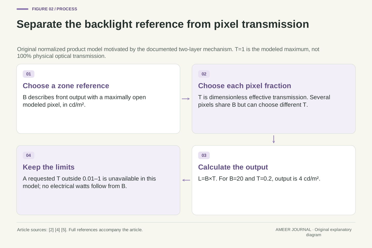
Call the zone's fully open reference brightness B. Call a pixel's allowed fraction of that reference T. Our output rule is B multiplied by T. For example, B=20 and T=0.2 produce 4 cd/m², a unit of screen luminance. Here T=1 means the model's maximum effective transmission, not that a real LCD passes every photon through all its layers. Defining B this way also avoids confusing the backlight's electrical power with the light measured at the front of a screen. No wattage follows from these assigned luminance values.
The source-backed mechanism is modulation of backlight through an LCD optical stack, not direct per-pixel emission from that backlight. EIZO's September 2018 white paper describes transmittance and multiple optical layers; VESA's FAQ identifies backlight level and LCD transparency as separate contributors to front-of-screen luminance. [4][5] These descriptions motivate a bounded product model, but supply none of its numeric coefficients or a claim that real spatial transport is a perfectly uniform scalar multiplication.
Define B_z in cd/m² as the reference output luminance for a maximally open modeled pixel in zone z. Let T_i be dimensionless effective transmission normalized to that maximum. Then L_i=B_zT_i for pixel i assigned to z. The normalization absorbs fixed optical factors; T_i=1 is not unit physical transmission through an actual stack. Thus B_z=20 cd/m² and T_i=0.2 give L_i=4 cd/m². Neither B_z nor L_i is electrical power, and no efficiency or energy-consumption result is derived from their numerical values.
Give every pixel the same declared range before comparing targets
Assign the imaginary zone a backlight range from zero to 100 cd/m² at its fully open reference. Each pixel can use a transmission fraction from 0.01 to 1. At a backlight level of 80, the largest available output is 80 and the smallest is 0.8. The pixel can reduce the light strongly, but it cannot make an arbitrarily small positive output while that shared backlight remains high. VESA discusses minimum LCD leakage as a limit on displayed black; our one-percent floor is an invented teaching value, not a typical specification. [5]
Assume the zone illuminates its assigned pixels uniformly and does not spill light into another zone. We also leave reflections, colour, rounding and power sharing out of the model. Those assumptions make the control problem visible without pretending to reproduce a complete panel. At any positive B, a pixel can choose an output between 0.01 times B and B. A desired output outside that interval cannot be recovered just by asking its LCD control to try harder. The later comparisons keep these same bounds unless a change is stated explicitly.
Set 0≤B_z≤100 cd/m² and 0.01≤T_i≤1 for every modeled pixel. At fixed positive B_z, the attainable output interval is [0.01B_z,B_z]. The residual-transmission concept is consistent with VESA's discussion of LCD leakage, but the chosen floor and ceiling are original assumptions. [5] We assume uniform independent zones, a static monochrome scalar response, exact arithmetic and no ambient, spill, quantization or aggregate power constraint. These omissions define the problem being solved rather than hidden implementation claims.
For a positive target L_i, exact reproduction requires B_z≥L_i and B_z≤L_i/0.01, together with B_z≤100. All pixels in a shared zone must accept the same B_z, although their T_i values may differ. Feasibility therefore depends on the intersection of their permitted backlight intervals. If every target is zero, B_z=0 supplies that separate case. A positive target and a zero target in the same zone cannot both be exact under the assigned positive transmission floor. No universal real-panel black-level value is inferred.
A bright target of eighty conflicts with a dark target of one fifth
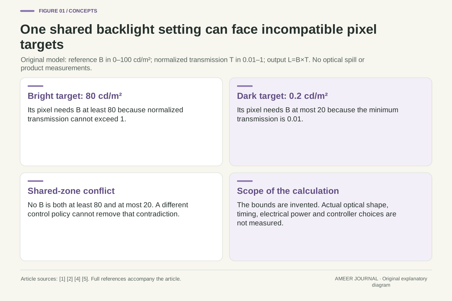
Give two pixels in one zone targets of 80 and 0.2 cd/m². The bright pixel needs a backlight reference of at least 80, because its maximum transmission fraction is one. The dark pixel needs a reference no higher than 20, because even one percent of 20 is already 0.2. No single number can be both at least 80 and at most 20. The conflict appears before choosing any local-dimming algorithm: it follows directly from the limits we assigned.
If we preserve the bright target by choosing B=80, the darker pixel would need a transmission fraction of 0.2 divided by 80, or 0.0025. That is below the allowed 0.01. At the floor it produces 0.8 cd/m² instead, four times its target. Apple's explanation connects the larger zone size with local-dimming blooming trade-offs. [1] Our example isolates one shared-control cause of lifted dark output; it does not predict the width, visibility or detailed optical shape of a halo on a real display.
Use the original target pair (80,0.2) cd/m². The bright target allows B in [80,8000] before applying the hardware ceiling; the dark target allows B in [0.2,20]. Intersecting both with [0,100] leaves no value. Equivalently, the maximum target is 80 while the minimum target divided by the transmission floor is 20. This is an exact incompatibility within the model, not uncertainty about which optimization objective a manufacturer selected.
At the bright-preserving B=80, the required dark transmission is 0.0025=1/400, below the assigned 1/100 floor. Clamping at that floor yields 0.8 cd/m². The same-zone target ratio is 400, whereas the assigned transmission range provides at most 100 at a fixed positive B. Apple's zone-versus-pixel explanation supplies the relevant physical context. [1] The computed excess is not a measured blooming intensity or point-spread function. It is the output of the stated uniform shared-zone model, with optical transport deliberately excluded.
A different shared setting moves the error rather than removing it
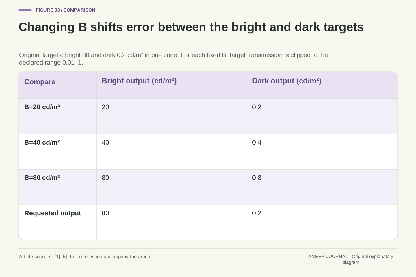
Try a lower backlight reference of 20. The dark pixel can now reach its 0.2 target at one-percent transmission, but the bright pixel can produce only 20 even when fully open. Try 40 instead: with each pixel pushed toward its target, the outputs are 40 and 0.4. At 80 they are 80 and 0.8. These three choices trade a dimmer highlight against a brighter dark area. None produces the requested pair of 80 and 0.2 under the original limits.
This does not identify the most pleasing picture. We have not assigned a preference for preserving highlights, shadow accuracy or any perceptual score. It identifies the options the declared controls can supply. Changing the LCD floor would change the problem: a floor of 0.0025 would make the original targets possible at B=80. That is a separate hypothetical improvement, not a setting our model says exists on your display. Distinguish changing the feasible range from selecting a different compromise inside the old range.
For a chosen positive B, use the explicit illustrative rule T_i=clamp(L_i/B,0.01,1). It moves each modeled pixel as close as this clipping rule permits to its target for that fixed B; it is not a manufacturer algorithm. B=20 gives outputs (20,0.2), B=40 gives (40,0.4), and B=80 gives (80,0.8), all in cd/m². The first sacrifices the highlight, the last preserves it while lifting the dark pixel, and the middle retains errors in both targets.
A perceptual or weighted-error optimum would need an additional objective, which is deliberately absent. The feasible-set result does not choose a preferred rendering policy. Separately reduce the transmission floor to 1/400 while keeping the cap and targets unchanged: the shared feasible interval becomes exactly B=80, with transmissions 1 and 1/400. This parameter change removes the contradiction. It shows that zone granularity and effective LCD modulation range are distinct design variables; more zones are not the only mathematical way to change this example's attainable outputs.
Independent zones can separate the conflicting requirements
Put the bright and dark pixels into independently controlled zones while keeping the same transmission range. The bright zone can use B=80 with its pixel fully open. The dark zone can use B=0.2, also with its pixel fully open. The two outputs now match their targets exactly. Local dimming, as VESA describes it, allows separate backlight segments to be adjusted independently. [2] Our numbers illustrate why that independence matters: the low target no longer forces the bright pixel's backlight reference downward.
Splitting a zone also cannot remove an old option in this ideal model. Every new smaller zone could simply copy the larger zone's former setting and reproduce its former outputs. It may offer additional options when different groups need different settings. That reasoning holds because we kept every other limit and optical assumption fixed. It is not a promise that any product with more advertised zones performs better in every image. Actual geometry, optical behavior and control choices still require evidence about the specific display.
Replace the shared B with independent B_bright and B_dark. Choosing (80,0.2) cd/m² and T_bright=T_dark=1 reproduces the target vector. The mechanism corresponds to VESA's distinction between a single globally controlled segment and independently adjustable local segments. [2] No extra total electrical-power allowance is calculated; this model never included an aggregate power limit. Its result concerns removal of a shared scalar constraint, not the efficiency or supply requirements of implementing that control physically.
A refinement argument makes the boundary precise. If a zone is subdivided and every new zone retains the old control range and optical assumptions, assign each child the old B. Every former feasible output remains reproducible, so the ideal feasible set cannot shrink. Strict expansion occurs for some target groupings, including our separated bright/dark pair. The conclusion does not compare two real panels whose transmission, light spread, drive limits or processing differ. Zone refinement is one controlled mathematical change, whereas a product comparison can change many parameters at once.
Two zones can describe two different spatial restrictions
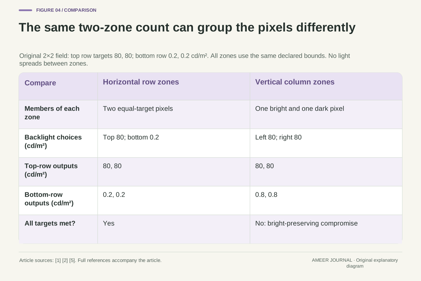
Imagine four pixels in a two-by-two square. Both top pixels should be at 80 cd/m² and both bottom pixels at 0.2. Give the top row one backlight zone and the bottom row another. The two zones can use references of 80 and 0.2, with all four pixels fully open. Every target is met. This is a deliberately tiny arrangement, used to expose which pixels share a control rather than to resemble the scale of a commercial panel.
Now keep two zones but make one cover the left column and the other the right. Each zone contains one bright target and one dark target, recreating the incompatible pair twice. If both preserve their bright pixels at B=80, the top row reaches 80 and the bottom row rises to 0.8. The number of zones is unchanged; their membership changed. Four independently controlled single-pixel zones would meet all four targets under the same ideal assumptions. A count without a spatial grouping therefore leaves an important part of the control problem unspecified.
Index the original 2×2 target field in row-major order as (80,80,0.2,0.2) cd/m². A horizontal partition groups indices (0,1) and (2,3). Assigning B_top=80 and B_bottom=0.2, with every T=1, satisfies the vector. The construction holds the target field and local bounds fixed while changing only the grouping. It is a finite illustration of the segmented-control distinction, not a source-derived commercial zone map. [2]
A vertical partition instead groups (0,2) and (1,3). Each group requires the empty shared interval derived earlier. Under the declared bright-preserving choice, the realized vector is (80,80,0.8,0.8). Both arrangements have two controls, but only the horizontal arrangement can reproduce this target exactly. Four singleton groups provide another refinement and recover the full vector. The result concerns membership and target compatibility; it does not model light leaking across physical zone boundaries or establish how a real panel shapes illumination near an edge.
A contrast ratio needs both a place and a time
At one positive backlight setting, our brightest and darkest permitted pixels differ by a factor of 100. For example, 80 divided by 0.8 is 100. In two independent zones, the simultaneous outputs 80 and 0.2 differ by 400. These ratios are both valid, but they compare different control arrangements. Neither can be substituted silently for the other. The value belongs to the particular bright and dark outputs being compared, not just to the word contrast on a specification sheet.
A third calculation uses two separate frames. Let one fully open bright frame produce 80, then let another frame use B=0.2 and one-percent transmission, producing 0.002. Their quotient is 40,000, but those two outputs were not displayed together. VESA's CTS 1.2 summary explicitly distinguishes single-image static contrast from active-dimming measurements that compare different images. [3] Our two-frame example is not that certification test. It shows why a large across-frame ratio cannot prove that the original shared zone can show an 80 highlight beside a 0.2 dark pixel.
For any fixed positive B in the original zone, L_max/L_min=(B×1)/(B×0.01)=100. The backlight factor cancels. Separate zones can realize 80/0.2=400 simultaneously because the numerator and denominator use different B values. This does not change the normalized transmission range of either LCD pixel. It changes the spatial control boundary used in the contrast calculation, which must accompany the result.
For a separate temporal comparison, take L_bright=80 from one frame and L_dark=0.2×0.01=0.002 cd/m² from another. The quotient is 40,000, with a positive denominator and no claim of simultaneous display. The actual CTS 1.2 summary distinguishes single-image static contrast from active dimming across different test images. [3] Our assigned frames reproduce none of its test patterns or procedures. Their sole purpose is to demonstrate that a cross-frame quotient supplies different evidence from a simultaneous within-zone or across-zone ratio.
An unchanged pixel can move if the two layers change separately
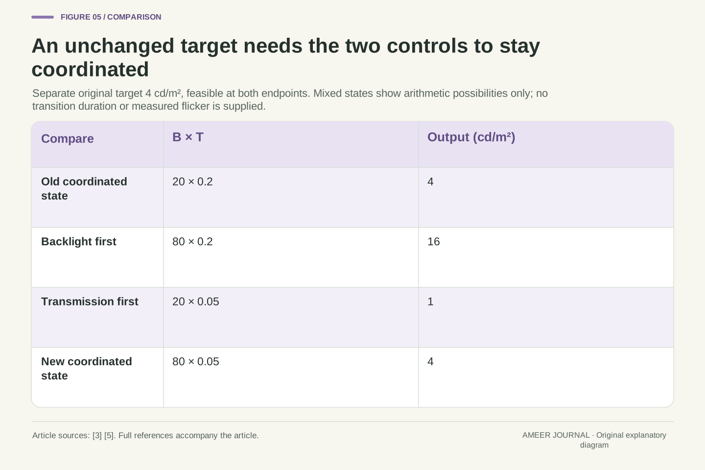
Use a separate, feasible target of 4 cd/m² for one pixel. It begins with B=20 and transmission 0.2. When another part of the scene needs the zone's reference to rise to 80, this pixel can stay at 4 if its transmission falls to 0.05. Both transmission values are allowed. VESA explains that backlight changes and LCD transparency must be coordinated to keep an otherwise unchanged part of a scene stable. [5] This example is different from the impossible 0.2 target inside the earlier bright zone.
The order matters in the arithmetic. If the backlight reaches 80 while the pixel still transmits 0.2, its output becomes 16. If transmission falls to 0.05 while the backlight remains at 20, the output becomes 1. Once both new settings apply, it returns to 4. These are hypothetical mixed states, not measured flicker or predicted transition times. They explain why reaching the correct final setting is only part of the task. The scene can also require the two layers to remain appropriately coordinated on the way there.
Take an independently defined unchanged target L=4 cd/m². The initial pair (B,T)=(20,0.2) and final pair (80,0.05) both reproduce it, and both T values lie inside the assigned bounds. VESA's FAQ describes precisely the need to reduce transparency while increasing backlight in order to preserve an unchanged pixel's output. Its CTS 1.2 summary includes a subtitle-flicker evaluation of related coordination. [3][5] No duration or actual controller response is imported into our example.
The two possible mixed pairs yield 80×0.2=16 and 20×0.05=1 cd/m². The final coordinated product is 80×0.05=4. Thus endpoint feasibility does not establish a constant-output transition. These four arithmetic states are not a response curve, a model of LC dynamics or proof that a particular intermediate state occurs on a device. They identify why synchronization is an independent question after the static bounds have been satisfied. The original 0.2 target remains infeasible at B=80 under the old floor; timing cannot cure that separate contradiction.
A lower dark level and preserved shadow differences are separate results
Suppose another zone uses B=20 and three pixels transmit fractions of 0.01, 0.02 and 0.04. Their outputs are 0.2, 0.4 and 0.8 cd/m², so three shadow levels remain different. If a hypothetical rendering rule sends all three pixels to the minimum fraction of 0.01, all three become 0.2. The distinctions have disappeared even though the image may look darker. VESA calls loss of shadow distinctions black crush and discusses it separately from the LCD's minimum leakage level. [5]
Dimming the shared reference to 10 while keeping the original three fractions gives a different result: 0.1, 0.2 and 0.4. The levels are still distinct, but they no longer match the originally requested brightnesses. These two operations should not be described as the same improvement. One collapses differences; the other scales them in this model. The CTS 1.2 summary includes a shadow-detail check as well as black-level and contrast evaluations. [3] A darker minimum on its own cannot establish that every dark part of an image was reproduced accurately.
At B=20, use T=(0.01,0.02,0.04), giving L=(0.2,0.4,0.8) cd/m². The output vector contains three distinct values. A separately stipulated clipping policy that maps every T to the floor produces (0.2,0.2,0.2), destroying that distinction. VESA's FAQ separates shadow discrimination from the minimum luminance caused by LCD leakage. [5] Our positive floor does not require the numerical value zero to be used as the display's darkest modeled output.
By contrast, hold the original T vector and halve B to 10. The result (0.1,0.2,0.4) preserves distinctness and relative ratios while changing every nonzero target value. Neither operation establishes accurate tone reproduction merely by lowering some luminances. The CTS 1.2 description identifies shadow-detail testing separately from other black-level and contrast measurements. [3] This example models no encoded transfer function, bit depth or perceptual visibility threshold; it distinguishes exact equality, preserved differences and collapse within the stated scalar representation.
Read the test that produced a claim, not only the component count
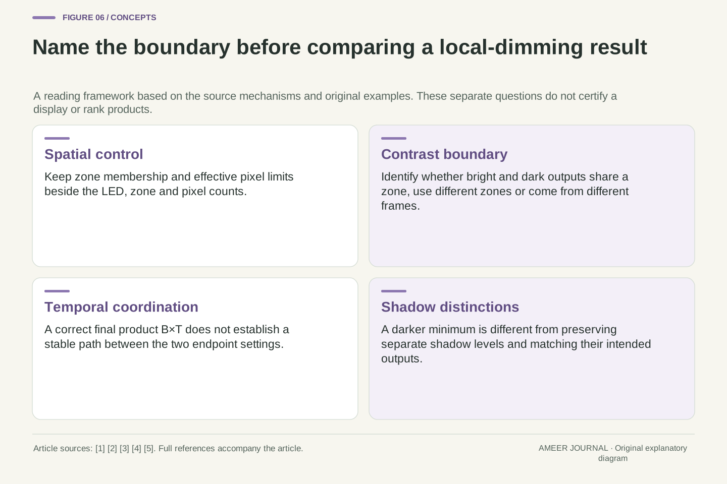
A useful MiniLED comparison therefore needs more than the number of small LEDs behind the panel. Ask what groups are independently controlled, what output pattern was being shown and whether the quoted bright and dark values occurred together. VESA's retrieved performance summary identifies itself as CTS 1.2, released in May 2024, and describes different tests for black level, static contrast and active dimming. [3] Those names are evidence boundaries. A result from one should not be turned into a result for another without the corresponding measurement.
Time is another boundary. The same summary describes a subtitle-flicker test concerned with keeping other scene elements stable as luminance changes elsewhere. [3] That question is not answered by a correct final contrast ratio. Nor does a named component count establish the optical behavior of the complete panel: EIZO's technical paper describes multiple layers with their own properties. [4] Our small model explains why these details are worth separating; it does not certify a display, prescribe a home measurement procedure or reconstruct an undocumented local-dimming algorithm.
Preserve the specification version and the measurement's spatial and temporal definition. The actual retrieved VESA summary is identified as CTS 1.2, released 7 May 2024. It distinguishes black-level, single-image static-contrast and different-image active-dimming evaluations. [3] This article uses those stated purposes, not numerical thresholds inferred from flattened table cells or an assertion that any named device has passed them. The original ratios are analytical examples outside the certification procedure.
The same summary's subtitle-flicker description concerns coupled backlight/transparency modulation and stability of scene elements whose targets do not change. [3] It adds a different measurement dimension from a static ratio. Physical optical layers also matter, as the EIZO white paper explains. [4] Consequently, zone count, effective modulation range, spatial light distribution, temporal coordination and measured output should remain separate fields. No one of them is a sufficient statistic for the others, and the current evidence does not quantify the contribution of every omitted physical effect.
Keep the shared control beside the output it is meant to produce
Start a MiniLED claim with the target picture and the grouping: which pixels share a backlight setting? Then keep the pixel transmission limits beside that setting. Our 80-and-0.2 example failed in one zone because its required backlight intervals did not overlap; separating the pixels into independent zones removed that particular conflict. A different two-zone geometry put the conflict back. These results arise from declared controls and targets, so they can be explained without inventing a product test or assuming that a high zone count settles every image.
Finally, name what the evidence measures. A simultaneous bright/dark pair, a quotient from different frames, a stable transition and preserved shadow differences are different observations. The primary descriptions of local dimming and the versioned tests support keeping those boundaries visible. [1][2][3][5] This gives a useful interpretation of a bright object lifting a nearby dark area: examine the shared control and its limits first, then ask what the actual optics and timing add. A component label becomes informative when it is tied to the specific output question it can answer.
A complete interpretation names the target field, zone membership, control ranges and actual observation. In the original model, feasibility is the intersection of per-pixel backlight intervals; splitting or rearranging groups changes that intersection without changing the pixel targets. The shared pair, spatial partition comparison and refinement argument identify distinct consequences of control granularity. They are not an aggregate OLED power model or a claim that a mean luminance reconstructs a spatial field.
Retain the boundary of every reported result: fixed-zone simultaneous contrast, independent-zone contrast, cross-frame ratio, transition stability or shadow discrimination. VESA and Apple's mechanism descriptions and the CTS 1.2 test purposes separate these questions. [1][2][3][5] The four temporal products also show that satisfying the final static equations does not determine the path taken between them. Reading a zone-count claim alongside those missing variables makes its limits explicit while leaving genuinely device-specific questions to documented implementations and appropriately matched measurements.
Sources & further reading
Explore the references behind this guide. External pages may change after our review.
- About the Liquid Retina XDR display on iPad Pro - Apple SupportApple Support · Accessed 7 Nov 2026
- LCD Dimming in HDR Displays Explained - VESA Certified DisplayHDR™VESA DisplayHDR · Accessed 7 Nov 2026
- Performance Criteria 1.2 TB1400 260708 - VESA Certified DisplayHDR™VESA DisplayHDR · Accessed 7 Nov 2026
- Advanced Image Quality Stabilization: ColorEdge, No.18-001 Revision A (September 2018)EIZO · Accessed 7 Nov 2026
- FAQ - VESA Certified DisplayHDR™VESA DisplayHDR · Accessed 7 Nov 2026
Article updated 7 Nov 2026.
Found something we should revisit?
Good explanations get better with thoughtful feedback.