What you’ll take away
- Active-image demand depends on complete-frame rate and bits per pixel as well as resolution.
- Four HBR3 lanes provide 32.4 Gbps raw and a 25.92 Gbps coding-adjusted ceiling; those rates have different meanings.
- Exceeding the active-data bound rejects a specified uncompressed case, while falling below it does not establish a complete working mode.
- Lane allocation, timing, multiple streams and compression change different parts of the account.
- A mathematical frame-rate upper bound is not an enumerated, selected or tested display mode.
A stream below the raw link rate can still exceed its video budget
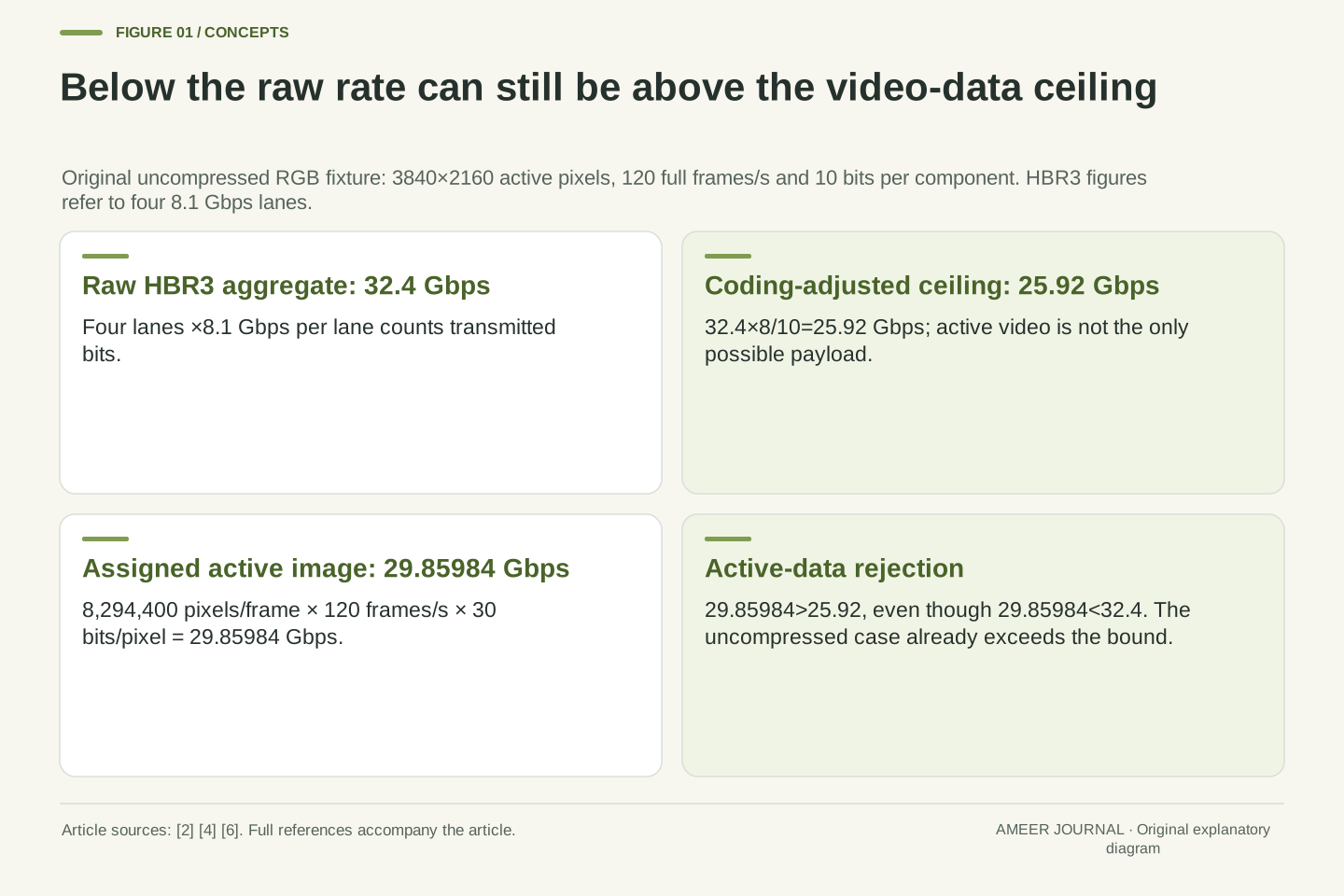
Imagine an uncompressed picture stream containing 3840 by 2160 active pixels, sent 120 times each second, with three ten-bit colour components per pixel. Its active-image data alone amounts to about 29.86 billion bits per second. That is less than a 32.4 Gbps link label, yet it already exceeds the 25.92 Gbps coding-adjusted ceiling of a four-lane HBR3 DisplayPort connection. VESA's January 2017 explanation explicitly separates those two link figures. [2] Comparing the picture with the larger number would answer the wrong capacity question.
The calculation here is an original paper example, not a monitor or cable test. All picture formats and timing examples are assigned, and we assume the named link configuration is established. We will separate active-image data, channel coding, lane allocation and shared transport before discussing compression. The aim is to show what a bandwidth comparison can rule out, and why a number below an upper limit still needs the rest of the configuration before it can establish a working display mode.
A raw serial-link rate and a video-data budget have different accounting boundaries. For four HBR3 lanes, VESA's dated January 2017 description gives 4×8.1=32.4 Gbps raw and 25.92 Gbps combined audio/video payload capacity. [2] Our original uncompressed RGB fixture, 3840×2160 active pixels at 120 frames/s with 10 bits per component, requires 29.85984 Gbps for active samples alone. It is below the raw rate but above the coding-adjusted ceiling, so the first comparison cannot establish feasibility.
This is a necessary-condition analysis of stipulated streams and link configurations. No mode enumeration, link training, cable test or display measurement was performed. We assume complete progressive frames, three full-resolution RGB components per pixel and no compression unless a later case explicitly changes the representation. The calculation does not reproduce every transport allocation or timing rule. HBR3 is deliberately named: its coding ratio is not a rule for all DisplayPort generations, and the existence of a specification feature is not evidence that an arbitrary device pair implements it.
Count components before multiplying by the image rate
A ten-bit colour component is not a ten-bit pixel in this example. Each pixel has one red, one green and one blue value, so three components at ten bits each require thirty bits. At eight bits per component, the corresponding total is twenty-four. Intel's bandwidth guidance identifies resolution, refresh rate and the bits-per-pixel factor as separate inputs. [4] Keeping those inputs visible prevents a colour-depth label from being inserted into the formula with the wrong meaning.
Our thirty-bit count describes the assigned uncompressed picture representation. It does not describe a file's size, a computer's memory alignment or an extra transparency channel. Other representations can count samples differently: VESA's DSC documentation distinguishes native subsampled formats from RGB conversion. [5] We keep those alternatives outside this RGB calculation. Changing from eight to ten bits per component raises its sample count by 30 divided by 24, or 25 percent, even though the width, height and frame rate remain exactly the same.
Let c be bits per component and let b be bits per active pixel in the specified RGB representation. With three full-resolution components and no alpha or padding in this sample account, b=3c. Thus c=8 gives b=24, while c=10 gives b=30. Intel's guidance treats the colour-depth factor in bits per pixel as a separate bandwidth input. [4] Confusing c with b would undercount this representation by a factor of three.
This is a count of active image information under the declared format, not the stride of a framebuffer or an on-disk image encoding. Native subsampled formats and RGB are separate representations in VESA's DSC discussion. [5] We therefore do not transfer b=3c to every advertised colour format. For the two assigned RGB depths, the exact demand ratio is 30/24=5/4. A 25 percent increase in this sample demand says nothing by itself about perceived improvement, panel implementation or an application's source precision; those would require different evidence.
Build the active-image count from quantities with explicit units
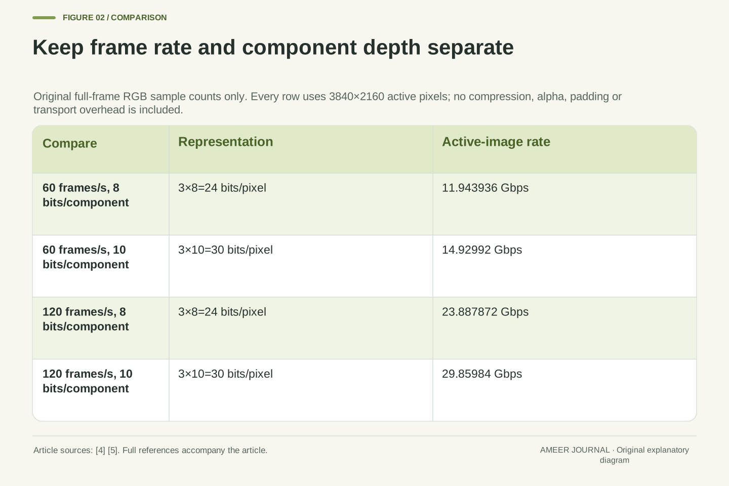
The assigned frame contains 3840×2160=8,294,400 active pixels. Sending 120 complete frames per second produces 995,328,000 active pixel samples per second. Multiplying by thirty bits per pixel gives 29,859,840,000 bits per second, or 29.85984 Gbps using a billion bits per gigabit. The dimensions cancel in a useful way: pixels per frame, frames per second and bits per pixel leave bits per second.
At sixty frames per second with the same thirty-bit pixels, the active-image rate becomes 14.92992 Gbps. At 120 frames with twenty-four-bit pixels, it becomes 23.887872 Gbps. Neither case changes the physical link merely by changing the picture requirement. These are counts of the assigned transmitted representation, not counts of different scenes a game creates. A repeated picture can still occupy another complete frame in this model. Partial updates, idle behaviour and a display's internal memory are outside this full-frame account.
For active dimensions W and H, complete-frame rate f and uncompressed active-pixel representation b, define A=WHfb. With W=3840, H=2160, f=120 s⁻¹ and b=30 bits/pixel, WH=8,294,400 pixels/frame and WHf=995,328,000 pixels/s. Therefore A=29.85984×10⁹ bits/s. All gigabit rates here use decimal 10⁹; the equation does not introduce a byte-to-bit conversion or a binary-gigabyte convention.
Holding W,H,b fixed and halving f gives A=14.92992 Gbps. Holding W,H,f fixed and changing b from 30 to 24 instead gives A=23.887872 Gbps. This factorization makes a changed requirement traceable to its actual input. It is an active-sample count, not a complete packet schedule, an application's render-completion rate or a claim that every picture is new. The stipulated stream repeatedly transports full frames; no panel-replay, selective-update or temporal-compression saving is silently credited to it. Those would be different operating assumptions requiring their own representation and support evidence.
Channel coding uses some of the transmitted bits
The raw link figure counts bits sent over the lanes. HBR3 uses eight-to-ten-bit channel coding: eight data bits are represented by ten transmitted bits. VESA's FAQ explicitly places HBR3 in that coding family and distinguishes it from the newer UHBR coding family. [6] For the named four-lane connection, 32.4 multiplied by eight tenths gives 25.92 Gbps. The larger figure cannot all be assigned to uncompressed picture samples.
This is a coding-adjusted ceiling, not a promise that every remaining bit belongs to the active image. The link also carries a structured display transport, and VESA describes the 25.92 Gbps figure as combined audio/video payload. [2] Our active-image requirement is only one part of that account. Keeping the ceiling generous is useful for a rejection test: if active samples alone already exceed it, adding the remaining requirements cannot rescue the uncompressed case. If they fall below it, further transport and mode checks are still needed.
For the named HBR3 channel-coding family, eight data bits occupy ten transmitted bits; VESA distinguishes this 8b/10b family from UHBR's 128b/132b coding. [6] Let L=4 lanes and r=8.1×10⁹ raw bits/s per lane. The raw aggregate is R=Lr=32.4 Gbps and the coding-adjusted bound is B=R×8/10=25.92 Gbps. VESA's HBR3 description gives the same raw and combined audio/video payload figures. [2]
B is used here as an upper bound available before the article resolves all remaining transport demands. It must not be identified with a measured active-video throughput. Control representation, audio and the actual allocation matter to a complete implementation. The necessary relation A≤B compares the uncompressed active sample count with this deliberately generous ceiling. Failure establishes that the stipulated uncompressed stream cannot fit that configuration even before additional requirements. Passing establishes only that this one inequality has not rejected it. It is not a complete sufficiency criterion for DisplayPort operation.
Twenty-percent coding cost and twenty-five-percent expansion can agree
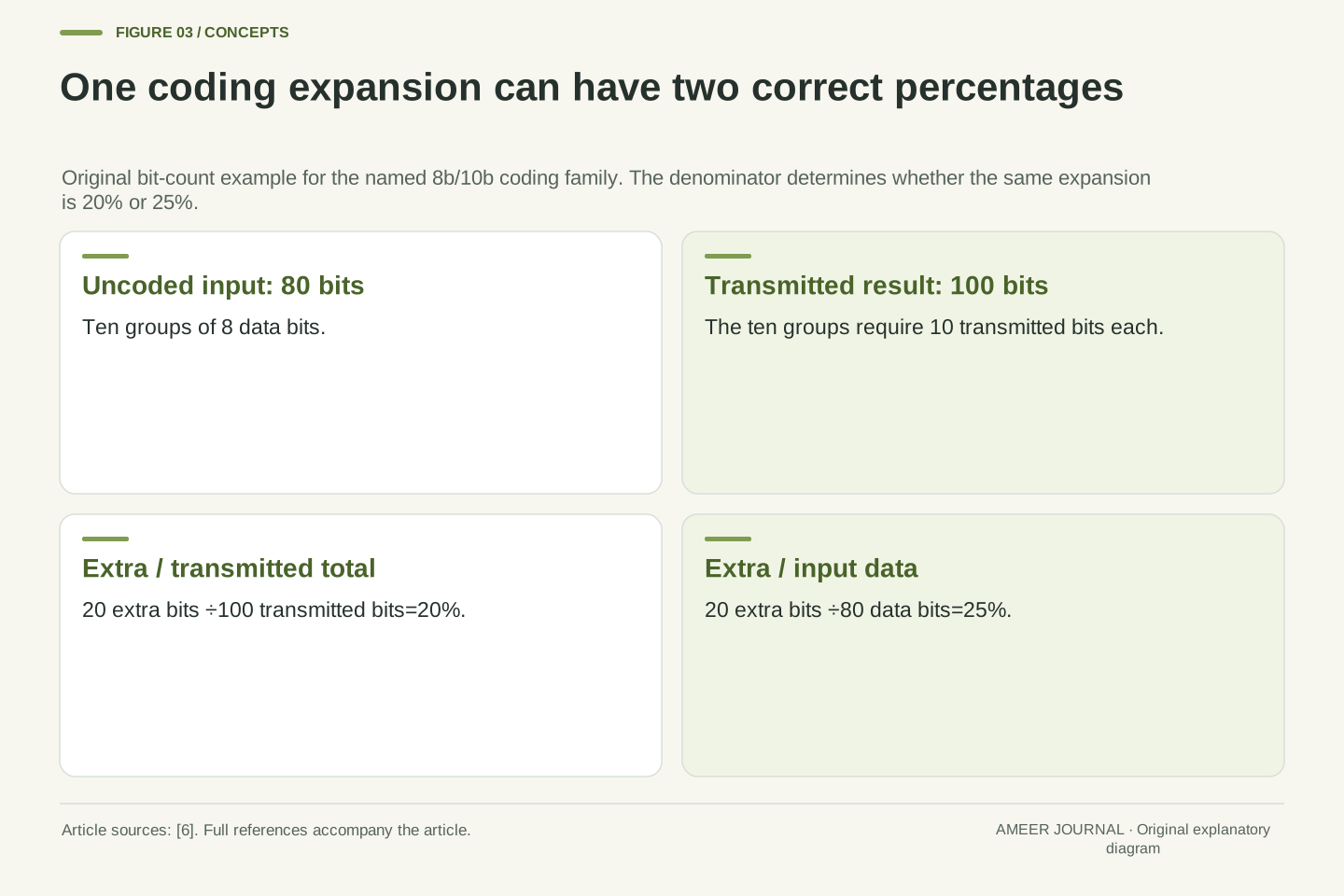
Consider an original group of eighty data bits. Under eight-to-ten coding, they require one hundred transmitted bits. Twenty of those transmitted bits are coding expansion. Twenty divided by one hundred is 20 percent of the transmitted total; twenty divided by eighty is 25 percent of the original data. These percentages describe the same expansion with different denominators. A disagreement between the two percentages need not mean that one calculation is wrong.
The direction of the calculation matters too. To find the data-bit ceiling from a raw rate, multiply by eight tenths. To find the coded rate required for a data-bit amount, multiply by ten eighths. Starting from the already adjusted 25.92 Gbps and deducting another 20 percent would count the same coding loss twice. Other genuine transport requirements remain separate, but they should be named and supported rather than hidden inside a second unexplained deduction for the very same channel code.
The 8b/10b mapping gives an exact coding efficiency η=8/10. [6] For an assigned 80 data bits, the coded count is 80/η=100 bits. The extra 20 bits are 20/100=1/5 of the transmitted total and 20/80=1/4 of the uncoded input. Thus 20 percent transmitted overhead and 25 percent expansion relative to data are compatible statements. They become contradictory only if their denominators are silently treated as identical.
The inverse transformations are B=ηR and R_required=A/η when considering channel coding alone. Applyingη twice to a rate already reported after this code would produce 25.92×0.8=20.736 Gbps, an incorrectly double-deducted figure for this particular operation. That observation does not imply that all other overhead is zero. It requires those other demands to be accounted for under their own definitions. Separating a code's expansion from subsequent transport allocation makes a bandwidth worksheet reproducible, whereas successive unlabelled safety percentages can obscure what the inputs originally represented.
A failed bound and an unfailed bound support different conclusions
Return to the thirty-bit, 120-frame example. Its active-image requirement is 29.85984 Gbps, while the coding-adjusted bound is 25.92. The difference is 3.93984 Gbps, so the active image alone is 15.2 percent above that bound. The original raw-rate comparison looked acceptable only because it included bits that cannot all carry image information. This is a definite rejection of the assigned uncompressed case on that four-lane HBR3 configuration.
Changing only the RGB component depth to eight bits lowers the active-image count to 23.887872 Gbps. The arithmetic difference below the ceiling is now 2.032128 Gbps. That remaining difference is not measured spare capacity and does not prove that every required timing and transport detail fits. It is room left in this preliminary account. A useful report would therefore say which case the active-data bound rejects and which case still needs configuration evidence, instead of marking every smaller number as a verified display mode.
For the 30-bpp fixture, A−B=29.85984−25.92=3.93984 Gbps and A/B=1.152. Because A>B, uncompressed active samples already require 15.2 percent more than the coding-adjusted bound. The failure does not depend on an estimate of blanking or audio load. It follows before those remaining demands are assigned, making it a valid necessary-condition rejection within the stipulated configuration.
For the 24-bpp variant at the same dimensions and frame rate, A=23.887872 Gbps and B−A=2.032128 Gbps. Here A/B=0.9216, leaving 7.84 percent of B unassigned by the active-image count. That is an arithmetic residual, not a measured transport margin or an allowed universal overhead percentage. Packet allocation, timing, representation support and the actual path still require evidence. The two outcomes are logically asymmetric: exceeding the upper bound proves failure of the specified case, while remaining below it merely leaves the case unresolved by this test.
The number of assigned lanes belongs beside the lane rate
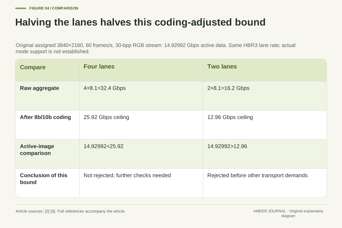
Four lanes at 8.1 Gbps each do not describe a connection using only two such lanes. With two, the raw total is 16.2 Gbps and the coding-adjusted bound is 12.96. VESA's historical HBR3 explanation discusses two-lane use in a USB-C alternate-mode arrangement, where other lanes can serve USB data. [2] The article does not assume that every dock or USB-C video connection uses that arrangement; it explains why the actual lane allocation is an input.
Our sixty-frame, thirty-bit RGB stream requires 14.92992 Gbps of active-image data. It is below the four-lane bound but above the two-lane bound. Keeping the same per-lane speed while halving the lane count therefore changes this preliminary result. A per-lane rating cannot replace the aggregate budget. Nor does a connector's shape establish how many lanes the selected path assigns to the display. The relevant record needs the established lane count and rate together, before any picture arithmetic is compared with them.
For the same HBR3 per-lane raw rate, L=2 gives R=2×8.1=16.2 Gbps and B₂=R×0.8=12.96 Gbps. VESA's 2017 description explicitly discusses a two-lane HBR3 alternate-mode use alongside USB operation. [2] That is support for the architectural possibility, not a universal classification of every dock, tunnel or USB-C link. Our two-lane case is an independently stipulated configuration.
At 3840×2160, 60 frames/s and 30 bits/pixel, A=14.92992 Gbps. Thus A≤25.92 but A>12.96. The second configuration fails the active-data bound even though the per-lane rate has not changed. A lower actual negotiated rate would similarly require a newB, rather than reuse of a port's maximum label. The calculation therefore binds L and r to the particular path being assessed. It does not derive either variable from a connector logo, a charging agreement or the number of physical output sockets on an intermediary.
Active dimensions do not contain the whole timing record
Microsoft's video-signal structure stores the active picture size separately from the size of the entire video signal, and also stores the pixel clock. [3] That is a useful reminder that the visible picture's dimensions do not contain every timing quantity. In an invented progressive raster, keep an active area of 3840 by 2160 but assign a total timing grid of 4000 by 2250 positions, repeated sixty times per second. The active area contributes 497,664,000 pixel samples per second, while the complete timing grid has 540,000,000 positions per second.
Those are different counts from the same assigned raster. The extra positions are not an additional visible border that the viewer necessarily sees. Nor should they automatically be treated as full RGB picture samples sent through DisplayPort: its transport is packetized. [6] This example identifies missing timing information; it does not construct an exact wire-demand formula. A complete mode decision needs the relevant timing and transport definitions together, rather than assuming that either active dimensions alone or a generic blanking multiplier settles the connection.
The documented DISPLAYCONFIG_VIDEO_SIGNAL_INFO distinguishes activeSize, totalSize and pixelRate; their native member descriptions identify the active portion, entire signal and pixel clock respectively. [3] Consider a separate assigned progressive raster with active 3840×2160, total 4000×2250 and frame frequency 60 Hz. Its active sample rate is 497.664 million pixels/s, whereas the defined total timing-position rate is 4000×2250×60=540 million positions/s. This is a rectangular raster construction, not an advertised VESA timing mode or an observed API result.
The distinction does not license multiplying every nonactive timing position by 30 RGB bits and calling the result exact DisplayPort wire traffic. VESA describes a packetized data structure. [6] Timing, active content and transport symbols require their appropriate relationship in a real mode calculation. We use the example only to show why W,H,f,b leave timing information unspecified. A software field naming the total signal size is also not a measurement of negotiated lane rate. Both records are useful, but neither can silently substitute for the other accounting boundary.
Two displays share a budget before they reach separate outputs
A dock can split one incoming display transport into multiple outgoing display paths. VESA describes the HBR3 bandwidth being shared among monitors using its multi-stream feature, and Intel's guidance calls for adding the relevant streams. [2][4] Separate output sockets do not create a second full copy of the incoming bandwidth. Each stream needs its own picture format and timing record, followed by an account of the shared part of the path.
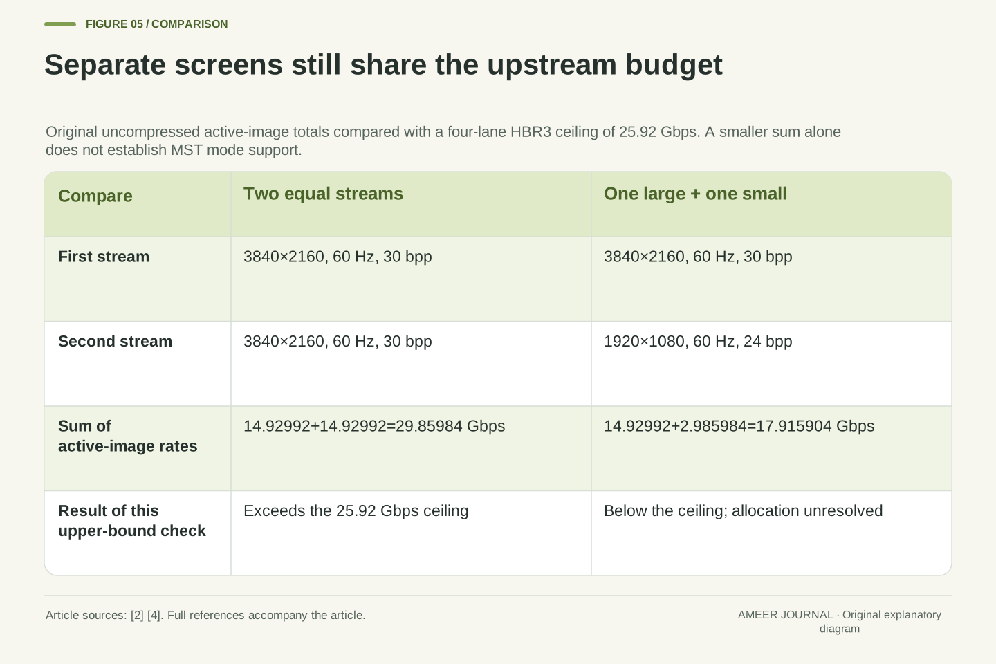
Assign two independent uncompressed 3840-by 2160 streams, each at sixty frames per second and thirty bits per pixel. Each active-image count is 14.92992 Gbps, but together they require 29.85984. That sum already exceeds the four-lane HBR3 bound. In a different pair, combine one such stream with 1920 by 1080 at sixty frames and twenty-four bits per pixel. The smaller stream adds 2.985984 Gbps, making 17.915904 Gbps in total. That pair survives the active-data comparison, while its actual multi-stream allocation and downstream support still need to be established.
For streams sharing one link, the necessary active-sample relation is ΣAᵢ≤B, before additional stream transport allocation is resolved. VESA's HBR3 account names shared multi-stream bandwidth, and Intel separately instructs readers to consider the sum of MST signals. [2][4] The relevant common resource is the shared upstream segment; independent downstream connectors do not each receive a fresh upstream B merely because they are physically separate.
For two assigned 3840×2160, 60 Hz, 30-bpp streams, ΣAᵢ=2×14.92992=29.85984 Gbps, exceeding 25.92. Each isolated stream survives the bound, but their joint requirement does not. A separate mixed pair gives 14.92992+(1920×1080×60×24)/10⁹=17.915904 Gbps. That is a necessary-bound survivor, not a multi-monitor compatibility result. Allocation granularity, each stream's timing and every downstream interface remain outside this sum. Equal aggregate active-bit counts also do not make one 120 Hz stream and two 60 Hz streams identical protocol schedules; only this particular preliminary total coincides.
Compression changes the represented stream, not the raw lane rate
Display Stream Compression, or DSC, provides another representation of the picture data. VESA describes it as a display-interface codec and distinguishes its supported colour formats and depths. [5] For a separate original calculation, suppose the thirty-bit RGB input is represented by an assigned ten encoded bits per active pixel. At 3840 by 2160 and 120 frames per second, the compressed active-image count is 9.95328 Gbps. The input-to-output data ratio is three to one; the physical lane rate has not tripled.
That assigned encoded rate does not prove that a source and display support the required codec configuration. Other transport requirements also remain outside it, so dividing the entire connection's traffic by three would be unjustified. VESA's meaning of visually lossless concerns typical observation under typical viewing conditions. [6] It is not a statement that every original component value is recovered bit for bit. Our example calculates an assigned data quantity; it provides no image-quality test, universal compression ratio or guarantee about a particular display.
Introduce an explicitly separate compressed-representation fixture with input b=30 bits per active pixel and assigned encoded q=10 bits per active pixel. VESA's DSC documentation describes a display-interface codec with format- and depth-specific capabilities. [5] The original encoded active rate isA_c=WHfq=3840×2160×120×10=9.95328 Gbps, and b/q=3. These are representation counts; neither L,r nor their raw link aggregate changes because q is smaller.
The assignment of q is not evidence that a particular encoder, decoder or negotiated configuration supports it. The compression ratio applies only to the defined image representation, not automatically to every transport or control contribution. VESA's FAQ describes visually lossless performance in perceptual, typical-observer terms. [6] That scope differs from mathematical bit-exact reconstruction, and its published descriptions are not our own codec evaluation. The correct follow-up is evidence for the actual compressed mode and its full transport requirements, not an assertion that every stream on a DSC-labelled path can be divided by an arbitrary constant.
Solving for a frame rate does not create a supported mode
The same arithmetic can be rearranged to find an upper bound. Divide the four-lane coding-adjusted 25.92 billion bits per second by 8,294,400 pixels per frame and thirty bits per pixel. The result is about 104.17 frames per second. This says that a higher full-frame rate already exceeds the generous active-data ceiling under those assumptions. It does not tell a display to accept 104.17 Hz or say how close an actual mode can approach the bound.
Using twenty-four bits per pixel raises this mathematical upper bound to about 130.21 frames per second. The change follows directly from reducing the number of bits assigned to each pixel. Real supported modes remain choices defined by the actual devices, timing and transport. Microsoft records a video signal's synchronization and timing fields separately, while VESA directs users to product documentation for supported features. [3][6] An algebraic limit is therefore a useful screening quantity, but it cannot manufacture a missing mode or certify an existing one.
Rearrange the necessary inequality WHfb≤B to obtain f≤B/(WHb). For B=25.92×10⁹ bits/s,WH=8,294,400 pixels/frame and b=30 bits/pixel, the bound is 625/6≈104.1667 frames/s. For b=24 it becomes 3125/24≈130.2083 frames/s. Both are ideal active-data upper bounds before remaining allocation requirements; neither is a selected, enumerated or measured DisplayPort mode.
The ratio of those bounds is 30/24=5/4, matching the inverse dependence on bits per pixel. This provides a consistency check on the earlier demand calculations without claiming a 25 percent gain in a real display's maximum supported rate. Timing fields and synchronization remain part of a mode record in Microsoft's definition, and supported product features require their own documentation. [3][6] A finite hardware mode list, an implementation constraint or additional transport demand can make the attainable result lower. The bound separates a mathematical impossibility from the additional work needed to establish a feasible implementation.
Keep the representation, timing and established link together
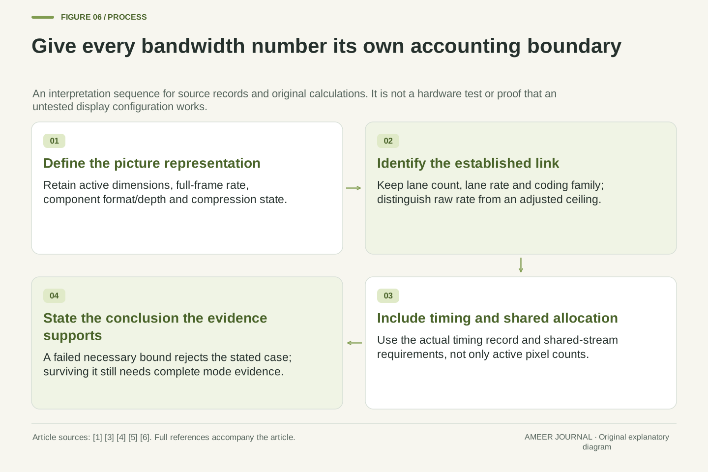
A meaningful bandwidth record starts with active width and height, complete-frame rate, colour representation and bits per component. Add compression state and its actual encoded format where relevant. Beside those picture inputs, keep the established lane count, lane rate and coding family, plus the shared upstream path if more than one display is present. Timing and supported endpoint modes complete the questions that our active-image count intentionally leaves open. [1][3][4][6]
Our original example supplies a clear result: 29.85984 Gbps of uncompressed active data cannot fit a 25.92 Gbps coding-adjusted ceiling, despite being below 32.4 Gbps raw. Reducing component depth, changing lane count, adding a second stream or changing representation alters a different part of the calculation. A case that remains below the ceiling needs further evidence rather than an automatic pass. Keeping those distinctions makes the numbers useful without turning a resolution label, a connector or a large advertised rate into a claim that the entire display configuration has been demonstrated.
Bind an interpretation to the active sample representation (W,H,f,b), the complete timing record, the established link tuple (L,r,coding), the compression configuration and the relevant shared-link topology. The cited VESA, Microsoft and Intel descriptions support these separate records; no single scalar specification substitutes for all of them. [1][3][4][6] In particular, retain whether a reported rate is raw, coding-adjusted, active-image demand or a complete allocated transport result.
The constructed 30-bpp 120 Hz case fails because A=29.85984 Gbps exceeds B=25.92 Gbps. The 24-bpp case leaves an arithmetic residual but not a demonstrated mode. Two 30-bpp 60 Hz streams reproduce the same excessive active total, while an assigned compressed representation changes the payload rather than the physical lane rate. The timing example shows another missing input without pretending that nonactive raster positions are automatically full RGB packets. These are precise conclusions from explicit assumptions. A real successful configuration still needs its actual capability, timing and transport evidence at every shared and downstream boundary.
Sources & further reading
Explore the references behind this guide. External pages may change after our review.
- Why DisplayPort - VESA - Interface Standards for The Display IndustryVESA · Accessed 7 Nov 2026
- VESA Rolls Out Early Certification Program for Video Source and Display Products Using HBR3 High-Bandwidth Link Rate - DisplayPortVESA / DisplayPort · Accessed 7 Nov 2026
- DISPLAYCONFIG_VIDEO_SIGNAL_INFO (wingdi.h) - Win32 apps | Microsoft LearnMicrosoft · Accessed 7 Nov 2026
- How to use Bandwidth to Determine the Best Video OutputIntel · Accessed 7 Nov 2026
- DSC - VESA - Interface Standards for The Display IndustryVESA · Accessed 7 Nov 2026
- FAQ - DisplayPortVESA / DisplayPort · Accessed 7 Nov 2026
Article updated 7 Nov 2026.
Found something we should revisit?
Good explanations get better with thoughtful feedback.