What you’ll take away
- A fixed source offer pairs one voltage with its own current capability; alternative offers are not additive.
- Match the device’s accepted voltages and current limits before comparing power allowances.
- An RDO object position refers to the associated advertised list, while raw fields require their documented units and types.
- Message acknowledgement, request acceptance and power readiness establish different stages.
- A completed power allowance is distinct from actual current draw and battery-side outcomes.
Several different wattages can describe the same connection
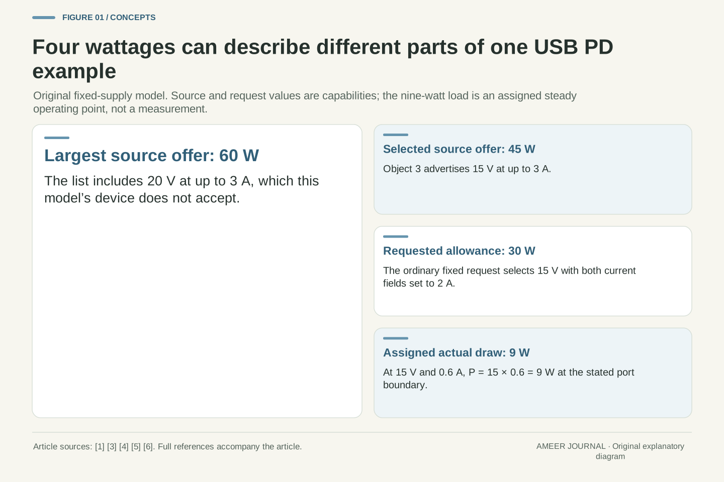
Imagine a USB power source whose largest advertised offer is sixty watts. A connected device selects a fifteen-volt offer capable of forty-five watts, requests an allowance of thirty watts, and later draws nine watts. Those four numbers can all be consistent. They describe the largest available offer, one selected offer, a requested arrangement and an actual operating condition. Microsoft's documented connector interfaces keep advertised capabilities and the currently negotiated contract as separate reports. [5][6]
This article follows an original fixed-voltage example to explain the differences. All electrical values and device restrictions are invented, not readings from a charger or phone. We use USB-IF's 2019 explanation of negotiation and Microsoft's documented UCM data types for specific concepts, while preserving their scope. The example does not cover programmable-voltage modes, every later specification extension or hardware compliance. Its practical question is narrower: how can a request identify a supported voltage and current, and what would that request still leave unknown about the device's behavior?
A source's largest advertised operating point, the selected source object's capability, the requested contract and instantaneous delivered power are different quantities. Our original example assigns them values of 60 W, 45 W, 30 W and 9 W respectively. No contradiction follows if each value retains its own reference. Microsoft's UCM documentation separately represents an advertised PDO array and notification of the current negotiated contract. [5][6] Neither representation is itself an instantaneous electrical measurement.
We examine fixed supply offers using the historical mechanism described in USB-IF's 2019 presentation and the retrieved UCM definitions. All numeric offers, sink restrictions and load points are stipulated. The example assumes compatible equipment and cable capability adequate for the advertised three-ampere offers; it does not validate those assumptions for real hardware. Programmable supplies, extended power modes, protection behavior, transient tolerances and other flags are outside the calculation. This boundary lets us derive the selection and unit arithmetic without presenting an old interface layout as a complete current USB PD implementation.
Read each offer as a voltage-and-current pair
Our source advertises four fixed offers in order: five volts at up to three amperes, nine volts at up to three, fifteen volts at up to three, and twenty volts at up to three. Multiplying voltage by current gives fifteen, twenty-seven, forty-five and sixty watts. These are alternative fixed operating points for the one connection. Adding all four wattages to produce 147 watts would count alternatives as though they were simultaneous outputs.
A Power Data Object, or PDO, is the structured description used here for one offer. Microsoft's fixed-supply definition has a voltage member and a maximum-current member; its partner-capability interface describes a list of such objects and the number of entries. [3][5] That structure matters more than the largest number printed beside a port. It preserves which current belongs to which voltage. Sixty watts alone does not tell us whether a particular fifteen-volt request fits, because the required pair must be present and satisfy the applicable limits.
Let the source list be S=[(5 V,3 A),(9 V,3 A),(15 V,3 A),(20 V,3 A)]. Each entry is a fixed-voltage candidate with its own current ceiling. Its nominal power bound is VjIs,j, giving [15,27,45,60] W. These bounds are not additive across a single selected fixed-supply connection. The sum 147 W has no role in this model's simultaneous port capability.
The documented UCM fixed PDO contains separate voltage and maximum-current fields; the partner-capability interface carries an array and a count. [3][5] A scalar maximum discards that association. Reconstructing an arbitrary current as 60 W divided by a preferred voltage would silently invent an offer that the array may not contain. Keep the list identity, order, type and per-entry values together. We treat the advertised entries as effective capabilities under the stipulated connection conditions, rather than deriving them from a packaging claim or independently guessing cable and multiport allocations.
The device has its own restrictions at each voltage
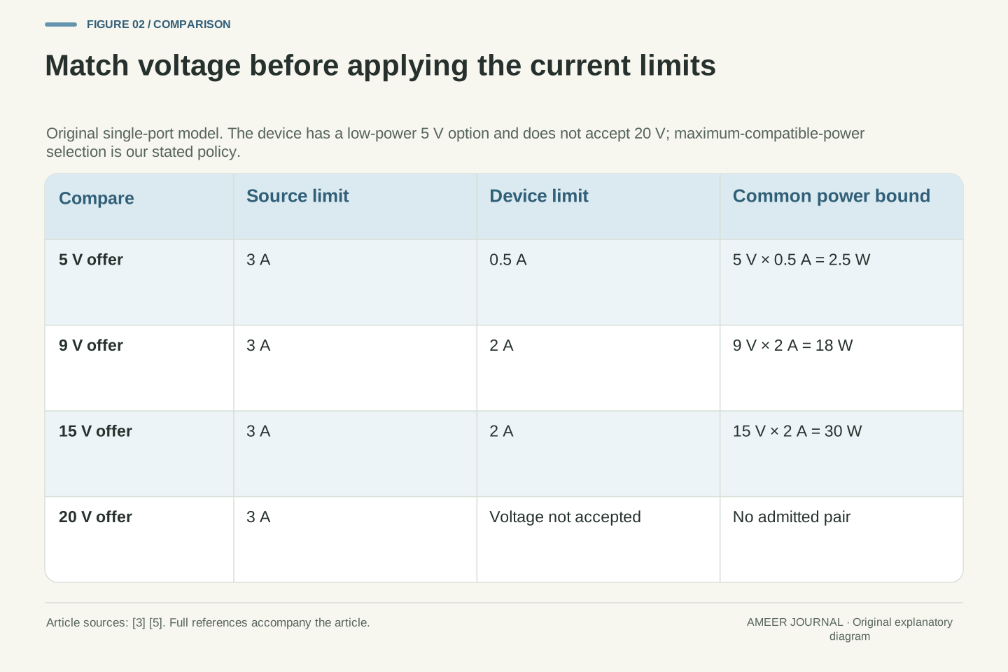
Give our hypothetical device these limits: it can use five volts at up to half an ampere in a low-power mode, nine volts at up to two amperes, or fifteen volts at up to two. It does not accept twenty volts in this model. At each acceptable voltage, the common allowance must respect both the source and the device. The resulting possibilities are 2.5 watts at five volts, eighteen at nine, and thirty at fifteen. The source's sixty-watt offer is outside this device's permitted voltage set.
For this worked example, choose the acceptable pair with the largest power allowance. That selects fifteen volts and two amperes. Choosing the largest compatible allowance is our stated selection rule, not a claim that every device always follows it. A product might have other operating goals or constraints. The important calculation happens before the choice: match the voltage, then apply the limits that belong to that voltage. A maximum device wattage and a maximum source wattage cannot replace this pair-by-pair check.
Define the sink's allowed fixed-voltage mapping as D(5 V)=0.5 A, D(9 V)=2 A and D(15 V)=2 A; 20 V is inadmissible. At an admitted source voltage Vj, use the model's common allowance Ij=min(Is,j,D(Vj)). The feasible pairs are therefore (5,0.5),(9,2),(15,2), with power bounds 2.5, 18 and 30 W. The fourth source entry is excluded by voltage compatibility before any wattage comparison.
Our policy selects the feasible pair maximizing VjIj, yielding the third source object and a 2 A allowance. This finite maximization is original model logic, not a normative sink-selection algorithm or a product prediction. In particular, the five-volt state is an assigned low-power option; its existence does not establish full operation or battery charging. Separate feasibility from preference: a pair must first satisfy every stated bound, after which a policy may choose among the admitted alternatives. This order prevents an attractive high-power entry from masking a disallowed voltage.
The request refers back to one source entry
The device can now refer to the third advertised object rather than sending the bare number thirty. In this list, the third object means fifteen volts with a source capability of three amperes. Our ordinary fixed-supply request uses two amperes for both its operating-current and maximum-operating-current fields. Microsoft's documented Request Data Object, or RDO, includes those fields and an object position. [4] The proposed thirty watts comes from fifteen volts multiplied by the requested two amperes.
Object position three does not mean three volts, three amperes or the third-highest wattage in every system. Its meaning depends on the last received advertised list. [7] The source's three-ampere capability also remains different from this request's two-ampere value. Keeping those records side by side explains why the selected offer can support forty-five watts while the proposed arrangement is only thirty. The proposal must still complete the relevant negotiation; writing down a plausible request does not establish that the source accepted it or finished changing its output.
Use ObjectPosition=3 with the current source list. The selected fixed PDO supplies the 15 V reference; its source ceiling remains 3 A. In the documented UCM FixedAndVariableRdo representation, set OperatingCurrentIn10mA and MaximumOperatingCurrentIn10mA to 200, both representing 2 A. [4] This example leaves GiveBack clear and does not exercise capability-mismatch or other flags. Its nominal requested allowance is 15 V×2 A=30 W.
An RDO reference points into the last received source-capability list. [7] Interpreting its object position requires the corresponding source-capability snapshot, rather than an assumed universal numbering of voltages. The request also does not erase the distinction between the selected source ceiling and the sink's requested allowance. Here these are 3 A and 2 A respectively. A complete transaction record would preserve the proposal and its outcome separately. Our arithmetic demonstrates a request consistent with the declared candidate bounds; it does not replace the source's acceptance decision or prove successful completion of a physical power transition.
The same raw number can encode two different electrical quantities
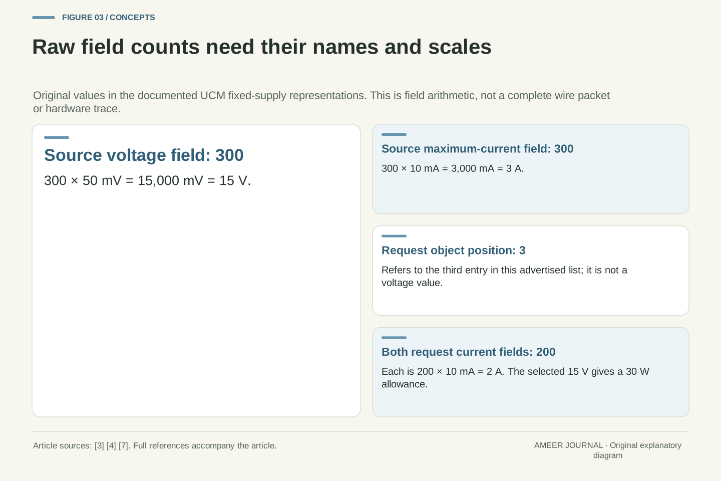
The displayed volts and amperes are not necessarily the integers stored in a data field. In Microsoft's documented fixed PDO, voltage is expressed in steps of fifty millivolts and maximum current in steps of ten milliamperes. [3] Our fifteen-volt, three-ampere offer therefore uses the number 300 in both members: 300×50 millivolts is 15,000 millivolts, or 15 volts; 300×10 milliamperes is 3,000 milliamperes, or 3 amperes. The matching integers do not mean matching physical quantities.
The request's two-ampere current fields use 200 steps of ten milliamperes. [4] Reading 200 as amperes would be a unit error, while reading 300 as a voltage without its scale would leave the quantity undefined. Keep the member name, unit and decoded value together. This is a representation exercise using original values, not a packet captured from a device. No software was compiled or controller configured. The example shows why a diagnostic number becomes useful only after its format has supplied the missing meaning.
For the documented fixed-supply fields, define raw integers nv and ni. Microsoft names their scales VoltageIn50mV and MaximumCurrentIn10mA. [3] Decode V=nv×0.05 V and Imax=ni×0.01 A. With nv=ni=300, the decoded pair is (15 V,3 A), whose nominal power bound is 45 W. Equal raw counts have different dimensions and scale factors.
The request current fields in the documented fixed/variable RDO use 10 mA units, so raw 200 decodes to 2 A for each chosen field. [4] These are field-value calculations, not construction of a complete 32-bit wire message: header, encoding order, reserved bits and unrelated flags are not supplied. The distinction avoids making a portable C bitfield-layout or full-protocol claim from a conceptual example. Preserve the raw value alongside the exact member and type when checking a decoding result. A plausible-looking wattage cannot validate a decoder that has silently used the wrong scale or object interpretation.
A field’s type limits the conclusions its value can support
The documented request types also show why the object kind matters. Their fixed-and-variable form has current members measured in ten milliamperes, whereas their battery-supply form has power members measured in 250 milliwatts. [4] In those different members, the same integer 200 would mean either two amperes or fifty watts. Neither result is ambiguous once the member is named. The ambiguity appears when someone keeps the integer and drops the type.
Field capacity is another separate question. Microsoft's fixed PDO assigns ten bits to each of its voltage and current members. [3] Ten bits can represent integers from zero through 1,023. Multiplying 1,023 by fifty millivolts gives 51.15 volts mathematically, but that does not make 51.15 volts an offer in our source list. A representable number does not establish a permitted operating point, cable capability or implemented mode. Decode the representation first, then check it against the actual list and the applicable system rules.
The UCM RDO union gives fixed/variable current fields 10 mA scaling and battery power fields 250 mW scaling. [4] Thus 200 units can decode to 2 A or 50 W depending on the named member. A union's overlapping representation does not make those dimensions interchangeable. Our request uses the ordinary fixed-current branch; it is not a PPS, adjustable-voltage or extended-power request.
The documented fixed PDO's voltage and maximum-current members each have a ten-bit width. [3] Their unsigned representational maximum is 2^10−1=1,023. Applying the voltage scale gives 51.15 V, but our fixed list contains only 5, 9, 15 and 20 V. The representational range is therefore not an enumeration of valid advertised voltages. Likewise, an integer that fits the field is not automatically valid under a specification revision or connection's hardware limits. Keep representation checks, capability checks and negotiation-state checks separate. Passing the first of those checks alone cannot establish that a requested operating point exists.
Receipt, acceptance and power readiness are different evidence
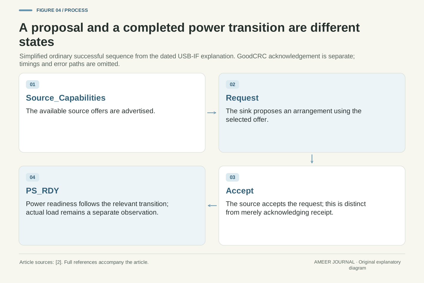
In the ordinary successful sequence shown by USB-IF, the source advertises capabilities, the sink makes a request, and the source accepts before reporting power ready. The presentation also distinguishes GoodCRC acknowledgement from the meaning of the message being acknowledged. [2] Receiving a request successfully is different from agreeing to provide its requested arrangement. Acceptance is also different from finishing the output transition.
Apply that distinction to our original example. After the capability list arrives, we know that a fifteen-volt offer was advertised. After the device sends its request, we know what it proposed. A receipt acknowledgement alone leaves acceptance unresolved. An acceptance records the decision, while the appropriate power-ready event completes this simplified successful-transition story. We do not assign transition durations, reproduce every protocol message or assume that a missing observation means a message never occurred. The point is to avoid promoting evidence of an earlier stage into proof that a later one has completed.
USB-IF's 2019 sequence distinguishes Source_Capabilities, Request, Accept and PS_RDY. Its GoodCRC explanation concerns message acknowledgement; its transition diagrams place acceptance before the later power-ready exchange. [2] A successful receipt acknowledgement is not semantic acceptance of the requested operating point, and Accept does not itself establish completion of the ensuing transition.
For the constructed third-object request, an observed advertisement establishes an offered candidate; an observed RDO establishes a proposal; the later outcomes establish additional state. These are evidentiary distinctions, not a full protocol-state-machine implementation. We omit acknowledgements from the simplified four-step figure without merging their meaning into Accept. No exact timing bound, error recovery, retry behavior or electrical transition waveform is inferred from this account. A trace fragment ending after Request cannot establish the completed contract simply because the candidate was arithmetically feasible. Conversely, a fragment lacking a captured event does not prove that the real system omitted it.
A thirty-watt allowance can accompany a nine-watt operating point
Suppose the ordinary negotiation has completed for fifteen volts and a two-ampere allowance. At an assigned load current of 0.6 amperes, the port supplies nine watts. At 1.2 amperes it supplies eighteen; at two it supplies thirty. The allowance has not changed across these three possible steady operating points. USB-IF describes power management that lets a device take the power its application requires. [1] A larger permitted amount does not force the device to consume that amount continuously.
These values belong to the stated port boundary. They do not tell us how much reaches a battery, how long charging will take, or whether the device is doing another energy-consuming task. Microsoft's contract-state notification describes a negotiated arrangement, not an ammeter reading. [6] If a real record contains only that arrangement, current draw remains unmeasured. A useful comparison would keep its measured voltage and current, their observation time and their electrical boundary alongside the contract information, so a changing load is not mistaken for a changed agreement.
At the stipulated steady 15 V boundary, use load points Iload∈{0.6,1.2,2} A under the same 2 A allowance. The corresponding powers P=VIload are 9, 18 and 30 W. The source's selected-object ceiling of 45 W and its largest-list ceiling of 60 W remain different references. Application-dependent power use is part of USB-IF's stated power-management purpose. [1]
An RDO's current parameters are not a time series of measured load. The documented connection-state notification reports the negotiated PD contract. [6] It does not by itself reveal actual VBUS voltage, load current, conversion loss or battery-side energy. The three values above are assigned operating points rather than measurements or a dynamic response model. They illustrate why an unchanged contract is compatible with different consumption. If later measurements are available, align their times and boundary before comparing them with the allowance. Otherwise, record the missing measurement explicitly instead of inferring it from the source's rating.
A twenty-seven-watt source gives this device an eighteen-watt option
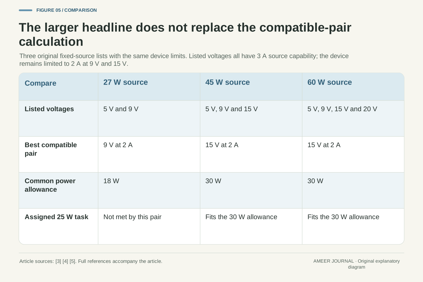
Now replace the original source with an invented one offering only five volts at three amperes and nine volts at three. Its largest offer is twenty-seven watts. Keep the device's restrictions unchanged. At five volts it can use only half an ampere; at nine it can use two. Its best compatible allowance is therefore eighteen watts. Taking the smaller of the two headline numbers, twenty-seven for the source and thirty for the device, would have predicted twenty-seven and missed the voltage-specific current limit.
A third invented source offers five, nine and fifteen volts, each at three amperes. Its largest offer is forty-five watts, yet the same device again reaches thirty at fifteen volts and two amperes. The original sixty-watt source and this forty-five-watt source therefore give the same largest compatible allowance in our model. The twenty-seven-watt one gives less. These outcomes follow from the listed pairs, not a universal rule that a certain printed wattage is sufficient for a particular product.
Define S27=[(5,3),(9,3)] in volts and amperes. Intersecting with the unchanged D mapping gives power bounds 2.5 and 18 W, so the policy selects 18 W. The scalar calculation min(27 W,30 W)=27 W is incorrect for this case: it discards the fact that the sink's 30 W capability belongs to 15 V, which S27 does not offer.
Define S45=[(5,3),(9,3),(15,3)]. Its maximum source bound is 45 W, but the feasible sink maximum is 30 W. S60 adds the 20 V,3 A entry; that entry remains inadmissible to D, so the sink maximum stays 30 W. These are explicit finite candidate calculations, not measured charger results or certification claims. They show both failure modes of a headline comparison: the smaller headline need not be attainable by the pair, and increasing the larger headline need not enlarge this sink's feasible set. The relevant input is the complete effective offer list paired with the sink's stated restrictions.
Check a task requirement at a voltage the device can use
Assign a separate hypothetical task that needs twenty-five watts at the same device-input boundary. At fifteen volts, that requirement corresponds to 25 divided by 15, or about 1.67 amperes. It fits the device's two-ampere limit and the source's three-ampere offer. The thirty-watt common allowance leaves five watts of allowance above the assigned requirement. This is a comparison of a requirement and a permitted amount; it is not a claim that the task will always draw the maximum.
At nine volts, twenty-five watts would require about 2.78 amperes. The twenty-seven-watt source could offer three at that voltage, but our device permits only two. The pair therefore cannot meet the assigned task requirement through that offer. The arithmetic pinpoints the limiting side without concluding how a real product would respond. It might have different modes or requirements, but those would need evidence. In this model, a source wattage larger than the task's wattage is insufficient because the device cannot use the necessary current at that offered voltage.
For the independent task requirement Preq=25 W, the 15 V current requirement is 25/15=5/3 A. It satisfies 5/3≤2≤3 A under D and the selected source entry. Relative to the 30 W common allowance, nominal power headroom is 5 W, equivalent to 1/3 A at 15 V. No battery efficiency or task duration is specified, so this is solely an input-power feasibility check.
At 9 V, Ireq=25/9 A≈2.7778 A. Although Ireq≤3 A at the source, it exceeds D(9 V)=2 A. The limiting common bound remains 18 W, below Preq. This case separates source sufficiency from pair sufficiency. We do not infer a particular fallback, warning, charging mode or runtime behavior from the failure: the constructed constraints only establish that the selected 9 V path cannot meet the stated 25 W requirement. Identifying the first violated bound is more informative than comparing two unqualified wattages and assuming every conversion of P/V is available.
The spaces between fixed offers do not create extra offers
The original source list contains nine and fifteen volts, but it contains no twelve-volt entry. Averaging those two voltages gives twelve mathematically; it does not add a new fixed offer to the list. Similarly, forty-five watts could be written as nine volts times five amperes, but our source's nine-volt entry allows only three. Rearranging a power equation does not change the advertised capability that the request must reference.
This is one reason the fixed-voltage boundary matters. USB-IF's overview separately describes an adjustable-voltage supply mode. [1] Its rules cannot be inferred by interpolating between the entries in our fixed list. The 2019 presentation also identifies cable rating as a condition on output-current capability. [2] We assumed that condition was already satisfied for our listed offers. A whole-charger power budget, another connected port or a different cable arrangement would require the appropriate effective capability record, rather than another calculation using the largest wattage alone.
The fixed candidate voltage set for S60 is {5,9,15,20} V. Its convex interval from 5 to 20 V is not the candidate set: 12 V lies inside that interval but outside this list. Likewise, the equation 45 W=9 V×5 A does not create a valid 9 V,5 A candidate when the advertised entry is 9 V,3 A. Algebraic equivalence of scalar power is insufficient for membership in a constrained operating-point set.
USB-IF separately describes adjustable-voltage operation, while the 2019 material identifies cable-rating dependence for current capability. [1][2] Those facts set boundaries, not extra candidates in our model. We neither interpolate a fixed PDO into an adjustable request nor infer cable capability from the connector's shape. The assumed list is the relevant effective advertisement for one connection. Shared supply allocation and changed capabilities would need their own contemporaneous input. Mathematical decoding, electrical feasibility and product support are related questions, but a result from one cannot silently answer all three.
Keep the list, request, outcome and measurement together
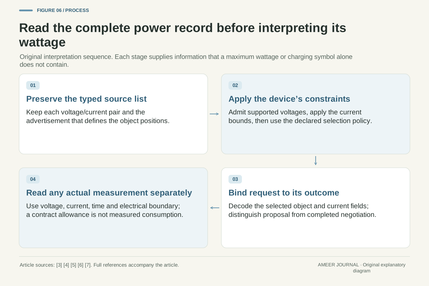
To make a USB PD power claim interpretable, preserve the advertised list and its object types, the device's relevant limits, the selected object and decoded request, and the observed negotiation outcome. Keep an actual voltage-and-current measurement separate if one exists. Microsoft's interfaces distinguish the source-capability list from contract-state reporting, and its capability documentation includes updates. [5][6] A request interpreted against an unrelated or outdated list could be assigned the wrong meaning.
Our example illustrates the complete distinction: the source list reaches sixty watts; its selected fifteen-volt entry supports forty-five; the proposed two-ampere arrangement permits thirty; an assigned 0.6-ampere load uses nine. A smaller source can remove a useful voltage even when its headline remains above a task's wattage. A larger source can add an offer the device cannot use. These conclusions come from the explicit pair and state records. If one of those records is unavailable for a real connection, leaving it unknown is more useful than filling the gap with a confident interpretation of a charging symbol.
Bind an interpretation to four records: the relevant typed source-capability list, the sink's applicable constraints, the requested and completed contract state, and any separately observed electrical sample. Microsoft's source-capability and connection-state interfaces make the distinction explicit, including capability updates. [5][6] Their existence does not promise that every consumer device exposes these records through a convenient diagnostic interface.
For the stipulated example, the references are Psource,max=60 W, Pselected,max=45 W, Prequest=30 W and an assigned Pload=9 W. Each value is reproducible only with its associated voltage, current and state meaning. The candidate-set calculation explains why S27 yields 18 W while S45 and S60 both yield 30 W for this sink. The event sequence explains why an advertised or requested pair is not yet evidence of the completed transition. Finally, the load calculation explains why a completed allowance is not measured consumption. Keeping all four accounts intact supports a precise conclusion without inferring a charger test, battery outcome or unsupported operating mode.
Sources & further reading
Explore the references behind this guide. External pages may change after our review.
- USB Charger (USB Power Delivery) | USB-IFUSB Implementers Forum · Accessed 7 Nov 2026
- USB Power Delivery — USB Developer Days 2019, Taipei, November 20, 2019USB Implementers Forum · Accessed 7 Nov 2026
- _UCM_PD_POWER_DATA_OBJECT (ucmtypes.h) - Windows drivers | Microsoft LearnMicrosoft · Accessed 7 Nov 2026
- _UCM_PD_REQUEST_DATA_OBJECT (ucmtypes.h) - Windows drivers | Microsoft LearnMicrosoft · Accessed 7 Nov 2026
- UcmConnectorPdPartnerSourceCaps function (ucmmanager.h) - Windows drivers | Microsoft LearnMicrosoft · Accessed 7 Nov 2026
- UcmConnectorPdConnectionStateChanged function (ucmmanager.h) - Windows drivers | Microsoft LearnMicrosoft · Accessed 7 Nov 2026
- USB PD negotiation during mismatch of capabilities - Infineon Developer CommunityInfineon · Accessed 7 Nov 2026
Article updated 7 Nov 2026.
Found something we should revisit?
Good explanations get better with thoughtful feedback.