What you’ll take away
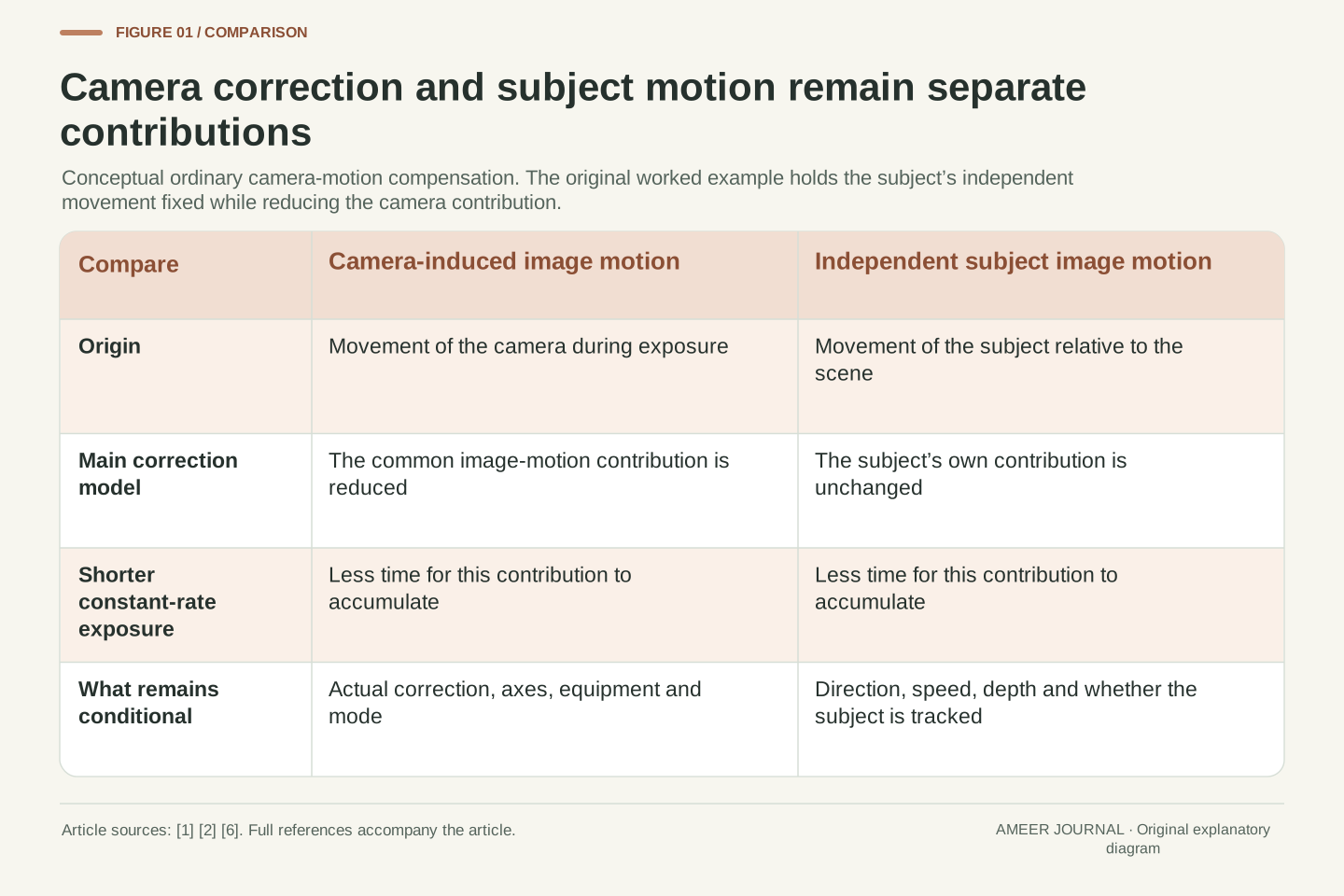
- Camera-motion correction and independent subject motion are different contributions to the recorded image path.
- A point can return to its starting position while still recording a nonzero path during exposure.
- Shortening the interval reduces both terms in a constant-rate model; correcting only camera motion leaves the independent subject term.
- A stop rating needs its method, configuration and conditions; it is not a guarantee that moving subjects will be sharp.
- Pixel travel, complete image sharpness and a standardized stabilization result are different quantities.
A steadier background can coexist with a blurred moving subject
Imagine photographing a stationary sign while someone walks past it. Camera stabilization might make the sign less blurred while the person's moving hand still leaves a streak. That result does not necessarily mean stabilization failed. The camera and the subject contribute different movement to the image. Canon describes optical stabilization as compensation for camera shake [1][2], while shutter duration also changes how subject movement is represented [4]. Correcting the camera's contribution does not automatically remove the subject's independent motion.
We will examine that distinction with original paper examples. Every distance, speed, pixel size and correction amount below is invented. The model describes a small part of the image near its centre during one common exposure interval. It does not simulate a complete lens, camera test, rolling sensor scan or computational editing system. The aim is to follow where an image point travels while light is being recorded, then understand why a useful stabilization feature can improve the photograph without making every moving object sharp.
An image point can move because the camera moves, because the scene point moves, or because both do. Ordinary camera-motion stabilization attempts to compensate for the camera-induced component; Canon's lens description explains this through detection and controlled displacement of an optical group [2]. A separate subject trajectory remains relevant to the integrated exposure. Thus improved stability of a stationary background and remaining blur on a moving foreground are compatible outcomes, not contradictory observations [1][4].
The following original models use near-axis pinhole projection, one exposure interval, fixed depth and explicitly stated constant image-motion rates. They are neither measured hardware performance nor a complete point-spread, rolling-shutter or image-processing model. In the main example, camera-induced and independent subject contributions are assigned the same image-axis sign. Later cases deliberately change one assumption at a time. This framework distinguishes the quantity a stabilizer reduces from the complete relative image path that determines the motion contribution during an exposure.
The correction acts on the image while the camera is moving
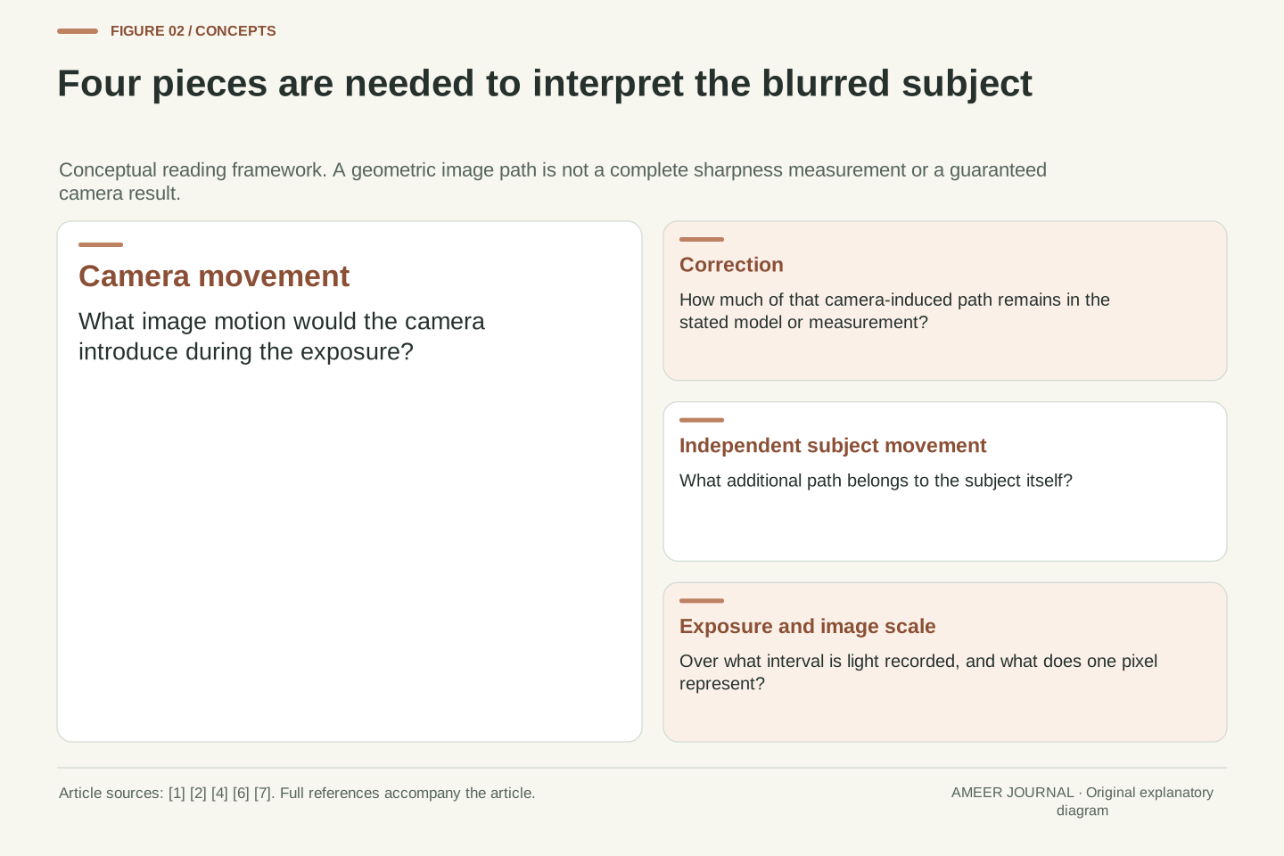
Canon's account of in-lens stabilization describes motion sensors detecting camera tilt, an actuator shifting a lens group across the optical axis, and position sensors providing feedback [2]. The purpose is to keep the projected image steadier as the camera moves. This is different from choosing a shorter exposure: the optical mechanism changes the image's path during the available time. A successful correction must relate to the movement as it happens, not simply return the lens group to a convenient position afterwards.
Other implementations move the image sensor, and some coordinate lens and body correction [1]. Those are different ways of acting on the camera-motion problem. Their presence does not justify adding separately advertised stop ratings as though they were independent amounts of light. The relevant result belongs to the supported camera, lens and mode together. Nor does a mechanism described for one model prove that every body in a product family has the same correction axes or functions. In the examples below, the remaining camera motion is an explicit assumption rather than a value inferred from a manufacturer's headline.
The retained Canon description identifies angular sensing, lateral displacement of the IS lens group and position feedback as parts of its optical correction loop [2]. Lens-group movement changes the optical mapping before the exposure is complete. Sensor-side correction acts through another physical coordinate, and coordinated control combines supported lens and body functions [1]. Neither mechanism should be confused with an exposure program that primarily reduces motion by shortening the recording interval.
For analysis, describe the residual image trajectory after correction rather than treating stabilization as an on/off guarantee. The control response must address movement over the exposure, and the achieved residual depends on the specified system and conditions. We will stipulate that residual directly; no controller bandwidth, actuator travel, measured success rate or commercial stop rating is being inferred. Coordinated mechanisms also do not make separate performance ratings arithmetically additive. A performance statement needs its own common test definition and configuration, whereas the presence of two mechanisms only establishes that two forms of correction can participate.
Returning to the starting point does not erase the recorded path
Consider a fictional point image that starts at pixel position zero, reaches position eight halfway through a 20-millisecond exposure, and returns to zero at the end. Its final position matches its first position. Nevertheless, light from that point has been recorded at intermediate positions. Zero final displacement is therefore not the same as no motion during exposure. The changing projected location matters, consistent with the image-position problem that optical correction addresses [2][7].
Three measurements describe different aspects of this path. The final-minus-initial displacement is zero pixels. The span from its smallest to largest position is eight pixels. The distance travelled along the outward and return journey is sixteen pixels. None of those numbers should silently replace another. The eight-pixel span is only a geometric extent in this toy example; it is not a measured sharpness score. The distribution of recorded light would also depend on how long the point spends at each position and how much light arrives there.
Endpoint displacement is insufficient to characterize an exposure-integrated image path. For a stipulated one-dimensional trajectory with positions 0, 8 and 0 pixels at times 0, 10 and 20 ms, the endpoint difference is zero while the geometric support spans eight pixels. Its total travelled distance is sixteen pixels. These are distinct mathematical functionals of the trajectory. The projected-position description follows the camera model [7]; the numbers and temporal path are original.
With light arriving during the motion, matching the final coordinate to the initial one does not cancel earlier exposure. Even the path's extent does not fully specify the intensity profile: dwell time, illumination and the underlying optical image matter. Consequently, our later constant-rate examples use travel as a simple geometric measure, not as an exact modulation-transfer or standardized image-degradation result. This distinction also explains why a visually steady composition or matching start/end framing alone cannot establish that the image remained stationary throughout the actual exposure.
Translate a small camera angle into image-plane travel
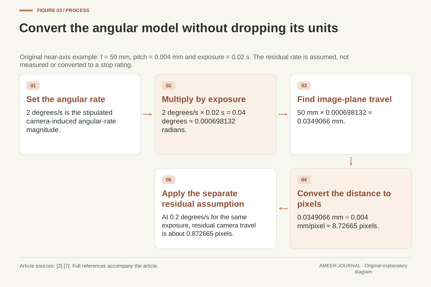
Give the ideal projection a focal-length parameter of 50 mm and a pixel spacing of 0.004 mm, or four micrometres. These are model inputs, not specifications measured from a real lens. Near the image centre, a small angular change moves the image by approximately the focal parameter multiplied by the angle in radians, following the projection geometry [7]. Suppose the camera-induced angular motion has a constant magnitude of two degrees per second during a 1/50-second exposure. The angular change is 0.04 degrees.
Converting that angle to radians and multiplying by 50 mm gives about 0.0349 mm of image-plane travel, or 34.9 micrometres. Dividing by the four-micrometre pixel spacing gives about 8.73 pixels. Now stipulate correction that leaves a residual angular-rate magnitude of 0.2 degrees per second. At the same exposure, the remaining camera contribution is about 0.873 pixels. The reduction is substantial within this model, but it says nothing yet about a moving subject. It also does not establish a stop rating or a universal acceptable amount of blur.
Use the ideal pinhole projection x=fX/Z and its near-axis angular form Δx≈fΔθ, with angles in radians [7]. Let f=50 mm, pixel pitch p=0.004 mm and exposure t=0.02 s. Then f/p=12,500 pixels/radian. For a stipulated constant camera-induced angular-rate magnitude of 2 degrees/s, Δθ=0.04 degrees≈0.000698132 radians, giving Δx≈0.0349066 mm and image travel Δx/p≈8.72665 pixels.
The parameter f belongs to the simplified projection model; it is not a measured image distance for a commercial 50 mm lens at finite focus. Stipulating a residual rate of 0.2 degrees/s after correction gives 0.004 degrees over the same exposure and approximately 0.872665 pixels of residual camera-induced travel. Thus this particular contribution falls by 90%. That percentage describes the declared constant-rate case, not a CIPA rating, an empirical correction curve or a statement that total subject blur must fall by the same proportion. The independent scene-motion term has not yet been included.
Add the motion that belongs to the subject itself
Let the subject move sideways at 0.3 metres per second while staying ten metres away in the model. During 0.02 seconds, it moves 0.006 metres: six millimetres in the scene. The ideal projection scales that sideways displacement by the focal parameter divided by the subject distance [7]. With our stated geometry, it becomes 0.03 mm on the image plane, or 7.5 pixels. This movement exists even if the camera's contribution is reduced very effectively.
For this example only, choose the two image movements to point in the same direction. Before correction, the moving subject's trace is about 8.73 plus 7.5, or 16.23 pixels. With the assumed residual camera motion, it is about 0.873 plus 7.5, or 8.37 pixels. The background benefits strongly, while the subject retains its own 7.5-pixel contribution. If movements point in different directions, their signed or two-dimensional paths must be combined accordingly; simply adding positive lengths would be wrong. The important fact is the separate motion, not one universal blur total.
At fixed depth Z=10 m, a constant transverse subject speed v=0.3 m/s gives an independent projected rate (f/p)(v/Z)=375 pixels/s in the chosen image coordinate. Over t=0.02 s, scene displacement is 0.006 m, projected displacement is 0.03 mm and pixel travel is 7.5. This follows from the ideal projection [7]. Camera-shake correction and movement of the subject are separately identifiable contributions, consistent with the terminology in the public CIPA draft [6].
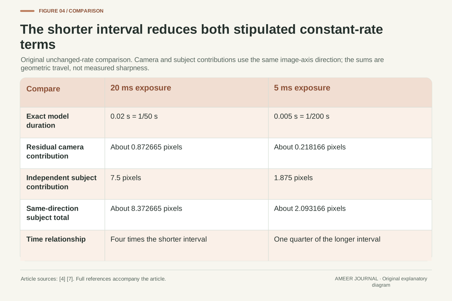
Assign both image-motion contributions positive signs in this particular one-dimensional case. The subject's uncorrected travel is approximately 8.72665+7.5=16.22665 pixels; after the stipulated correction it is 0.872665+7.5=8.372665 pixels. The residual background contribution and the independent subject contribution have different origins. A common compensating image shift cannot simultaneously remove two unequal relative trajectories in this model. The scalar sums are conditional on the chosen direction; general motion requires signed components or vectors, not the unconditional addition of magnitudes. No physical sharpness threshold follows from the numerical trace length alone.
A shorter exposure reduces both constant-motion contributions
Keep the same geometry, subject speed and residual camera rate, but shorten the exposure from 1/50 to 1/200 second. The interval falls from 20 to five milliseconds, so the constant-rate movements each have one quarter as much time. The residual camera contribution becomes about 0.218 pixels, and the independent subject contribution becomes 1.875 pixels. With the same chosen direction, the combined subject trace is about 2.093 pixels. This is a different change from correcting only the camera's movement.
The result is conditional on the unchanged rates. Real hand movement need not be constant, and a subject can change direction or speed. The calculation explains a mechanism rather than identifying a shutter setting that guarantees sharpness. Sony's shutter-priority guidance likewise links shutter duration to how moving objects are represented [4]. Exposure also has a light-budget consequence: with unchanged illumination and aperture, the shorter interval records light for less time. A complete photographic choice therefore needs both motion and exposure considerations, even though the present comparison isolates the motion paths.
At fixed projected rates, travel scales linearly with exposure duration. Replacing t=0.02 s with t=0.005 s divides both modeled terms by four: residual camera travel is about 0.218166 pixels and independent subject travel is 1.875 pixels. Their same-direction sum is approximately 2.093166 pixels. This transformation preserves the original geometry and rates; it is not an assertion that a real camera's residual motion is constant across different exposure settings.
The contrast is informative. Optical correction reduced the common camera component, while shortening the interval limits both components under the stated rate assumptions. The relation between shutter duration and recorded movement is supported by the manufacturer guide [4]. With fixed incident light and aperture, the integration time also changes the exposure amount, so the motion result does not provide a complete brightness or noise comparison. Nor does it address different row exposure times in a rolling scan. The model uses one common interval specifically to keep local motion integration separate from those additional timing and image-quality questions.
A stop rating is a time comparison with a defined measurement scope
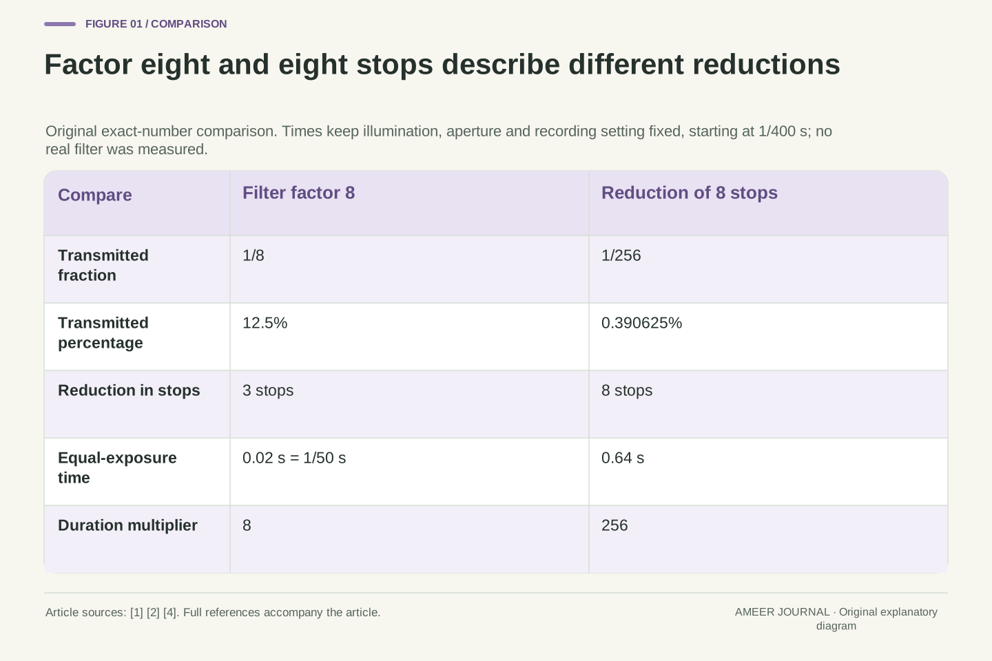
A hypothetical four-stop time advantage corresponds to a factor of sixteen in exposure duration. For a separate illustration, exact model times of 0.005 and 0.08 seconds differ by that factor. Our subject's independent 375-pixel-per-second movement would cover 1.875 pixels in the shorter interval and 30 pixels in the longer one. Even if a suitable stabilization result permitted the longer time for camera shake under its test conditions, that would not remove this subject's motion. This example does not rate the earlier 90% correction assumption.
CIPA's official page identifies its published optical-stabilization standard, while the openly downloadable 2024 document is explicitly a draft [5][6]. That draft distinguishes camera-induced blur from subject-motion correction and describes stops through exposure-time differences. It also distinguishes rounded display labels from the values used in calculations [6]. The documents help explain why a rating needs its method and conditions. They do not turn our paper example into a compliant test or establish that every photographer, focal length, mode and moving subject receives the same result.
For an exposure-time difference of N stops, the corresponding ideal time ratio is 2^N. In a separate original four-stop illustration, 0.005 s×16=0.08 s. Holding the independent subject rate at 375 pixels/s changes its trace from 1.875 to 30 pixels. This time comparison is distinct from the stipulated 90% reduction in one camera-motion component. Neither calculation establishes an actual camera's standardized stabilization performance.
The official CIPA landing page identifies the published DC-011-2024 optical standard and describes certified apparatus for claims of compliance [5]. The retrieved public PDF remains the marked 2024 draft [6]. Its scope excludes subject-motion correction, electronic stabilization and combinations of electronic and optical stabilization from the described optical still-image measurement; it also distinguishes theoretical exposure values from typical displayed shutter labels. These boundaries prevent a stop count from becoming a universal subject-freezing claim. We use the draft's definitions to interpret the quantity, not its wording as a complete current conformance procedure or a substitute for the conditions accompanying a real published result.
Following the subject deliberately changes the reference
For a separate ideal case, set aside the residual shake and imagine rotating the camera to follow the subject's sideways movement. At the model's ten-metre distance, its angular rate is about 0.03 radians per second, or 1.72 degrees per second. A matching local pan can remove that subject's first-order drift in the image. The stationary background then moves the other way: in this simplified case, by 7.5 pixels during 20 milliseconds. Making one part steadier does not make every part stationary.
This is why intentional movement needs a different interpretation from unwanted shake. The retrieved Nikon Z6III manual says its relevant Normal and Sport panning behavior corrects motion outside the pan; for a horizontal pan, it describes correction of vertical shake [3]. That is model- and lens-dependent guidance, not a rule for every stabilization system. The thought experiment explains the relative-motion geometry. It does not promise a successful panning photograph, a perfectly matched real subject trajectory or automatic recognition of every deliberate movement.
Consider a separate local first-order pan with residual shake omitted. The subject's angular rate is v/Z=0.03 radians/s≈1.71887 degrees/s. Matching that rate makes the subject's relative projected rate zero in the ideal near-axis model. The stationary background instead acquires a rate of −(f/p)(v/Z)=−375 pixels/s, or −7.5 pixels over 0.02 s [7]. These are local relative-motion terms, not an exact long-duration model of changing viewing geometry.
Stabilization behavior must therefore distinguish intentional tracking from the movement it is intended to suppress. Nikon's exact Z6III manual describes correcting the non-panning component in its stated Normal/Sport modes, with vertical correction during horizontal panning as its example [3]. This does not establish a universal pan detector, supported lens combination or success rate. The mathematical comparison likewise supplies no global claim that one object can be perfectly tracked across changing distance and direction. It shows that choosing a reference for correction changes which part of the scene retains image motion.
The motion axis and the actual configuration belong with the claim
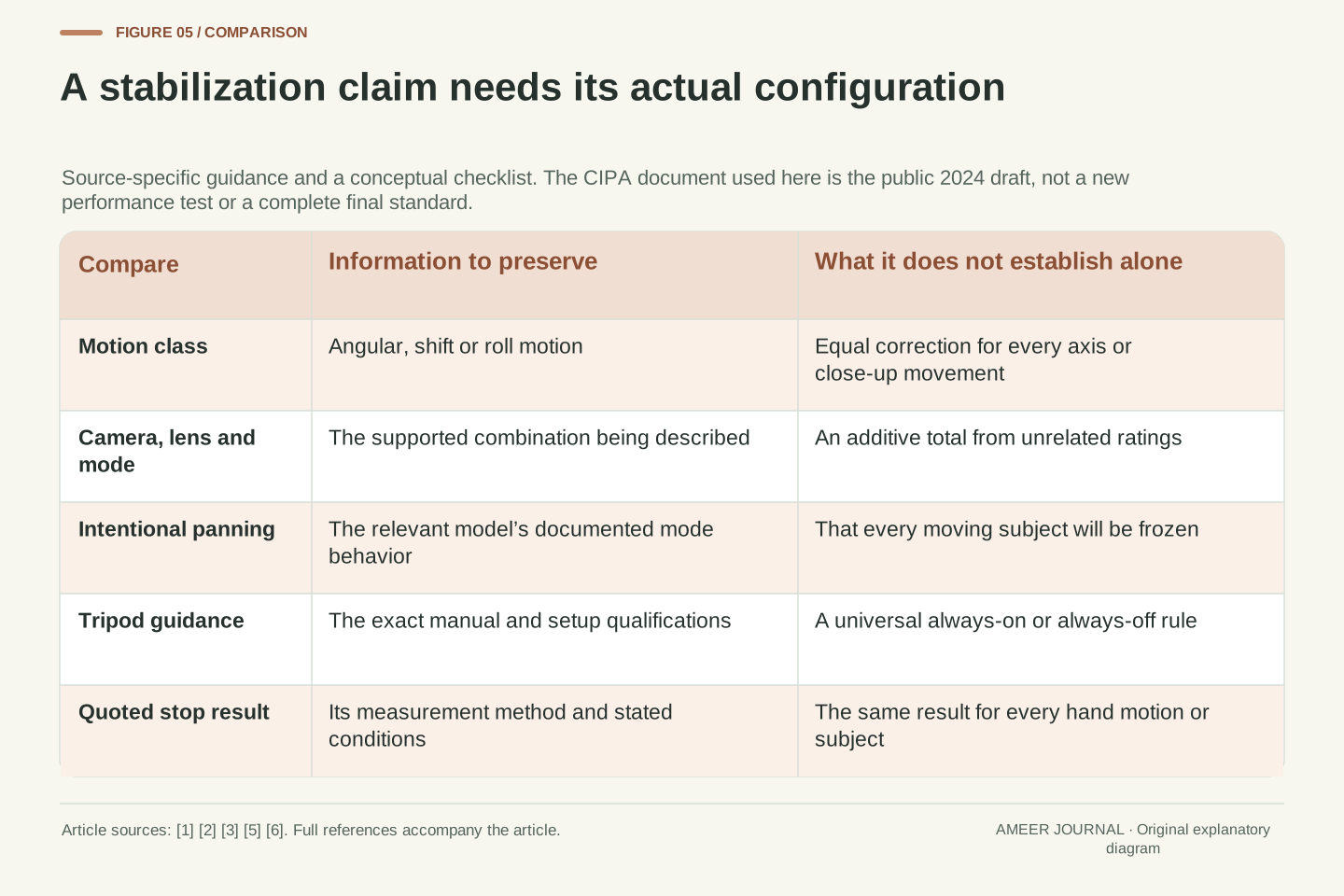
Our main calculation follows one angular direction. Real camera motion can also include sideways shifts and rotation around the lens axis. Canon distinguishes angular, shift and roll shake [1], and its Hybrid IS explanation describes additional sensing for shifts that matter in close-up work [2]. That product term refers to angular and shift sensing; it is different from the CIPA draft’s hybrid category combining electronic and optical stabilization [2][6]. A result for our one-axis distant-subject model does not establish performance for every macro movement or every corner of the frame. The type of movement belongs in the explanation, alongside how much correction is claimed.
Camera and lens settings also need their exact context. Nikon's Z6III page says available options vary with the lens, and its tripod discussion allows different choices depending on the setup [3]. That is evidence against turning a remembered rule into universal always-on or always-off advice. The CIPA draft similarly retains focal-length, mode and axis qualifications in its description guidance [6]. Read the supported configuration and the measurement conditions together. A feature name alone does not identify the same physical correction or the same test across all equipment.
The one-axis angular approximation excludes translational parallax, roll and more complex off-axis behavior. Canon's terminology distinguishes angular, shift and roll motion [1], while its Hybrid IS discussion adds linear-acceleration sensing to the angular information for close-range correction [2]. Canon’s name should not be conflated with the draft CIPA taxonomy’s hybrid category for electronic-plus-optical stabilization [2][6]. We do not infer performance for those additional axes from the scalar residual used in the worked example. Changing the motion class changes the model, not merely the units on the same number.
Configuration scope is equally material. The retrieved Z6III guidance makes option availability lens-dependent and qualifies tripod behavior rather than supplying a universal setting [3]. The public CIPA draft's description section retains mode, focal-length and correction-axis information [6]. These sources support reading a result as a statement about a defined configuration and method. They do not justify adding independent ratings, substituting a different lens, or generalizing one manual's panning and tripod behavior to every camera. The appropriate comparison preserves the actual equipment, mode and movement being assessed.
Pixel travel is useful geometry, not a complete sharpness score
A pixel count depends on the image scale. If the focal parameter doubles from 50 to 100 mm while the model's distance, motion and pixel spacing stay fixed, both projected movement contributions double. If instead only the pixel spacing halves, the same physical image-plane path spans twice as many pixels. Neither observation says that a particular real lens is worse or that more pixels create more physical camera movement. It says the scale used to report movement must remain visible [7].
Other causes of softness also remain separate. Stanford's camera notes distinguish the position of a projected point from the focusing geometry of a lens [7]. The CIPA draft distinguishes intrinsic image degradation from the handheld-motion quantity used in its framework [6]. Our 8.37-pixel trace is therefore not interchangeable with a focus error, a total image-quality measurement or a standardized stabilization score. A meaningful comparison preserves the original image scale, exposure and scene conditions instead of treating every blurred edge as proof of the same underlying problem.
The conversion from image-plane displacement to pixel travel is Δx/p. At fixed depth, motion and pitch, doubling f doubles the model's camera and subject terms; at fixed physical Δx, halving p doubles the reported pixel count. This follows from the projection and coordinate conversion [7]. It is not a comparison of equal framing, a lens-resolution test or a claim that increased sampling density worsens the physical motion. The denominator determines the representation.
Geometric trajectory extent also differs from complete optical blur and from a standardized measurement. Focus geometry is a separate part of the camera model [7], and the CIPA draft explicitly distinguishes intrinsic image degradation from its handheld-blur-related quantities [6]. Our calculations do not reproduce that measurement software, its chart analysis or its determination criterion. They likewise omit diffraction, optical aberrations, noise and processing. These omissions define the inference: a numerical path comparison explains motion contributions while leaving the full sharpness and appearance assessment to an appropriately specified image and measurement.
Ask which movement changed before judging the result
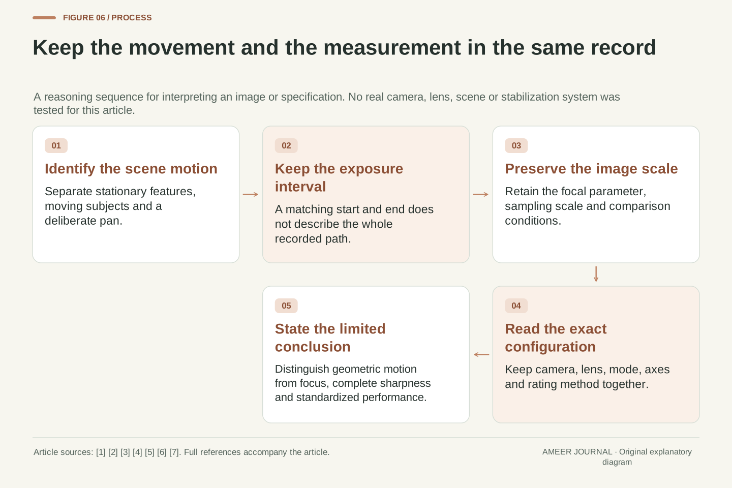
Start with the part of the scene you want to understand. Was it stationary, moving independently or being followed by a deliberate pan? Then keep the exposure duration, image scale and camera/lens mode with the observation. A steadier stationary background and a streaked moving subject can be a coherent outcome. In our main model, correction reduced the camera contribution from about 8.73 to 0.873 pixels while leaving 7.5 pixels of independent subject movement. The two parts explain the result more clearly than a single stabilization label.
When reading a published performance claim, check the stated method and configuration rather than transferring its number to every situation [3][5][6]. When interpreting an image, distinguish motion during exposure from focus and other image-quality effects [7]. The shorter-time example, the return-to-start path and the ideal pan each changed a different premise. Keeping those premises visible lets stabilization remain useful without asking it to solve a different problem. Its contribution is best understood through the motion it compensates, the motion left over and the interval during which both affect the recorded image.
A useful evidence record separates scene motion, camera-induced motion, correction behavior, integration time and image scale. It also identifies the actual camera/lens/mode and the definition of any quoted performance quantity [1][2][3][5][6]. This prevents several distinct observations from being collapsed into a single sharp-versus-blurred judgment. A stable endpoint does not specify the intervening path, and a reduced common camera term does not identify the remaining independent subject trajectory.
The original cases provide concrete checks: an out-and-back path can have zero net displacement but nonzero extent; the stipulated correction leaves the 7.5-pixel subject term unchanged; and shortening the common interval reduces both constant-rate terms. The separate stop and panning examples alter different assumptions and cannot be substituted for that result. Preserve these boundaries when interpreting a photograph or specification. Optical stabilization can improve the component it addresses while a moving subject, a different motion axis or another image-formation effect remains the limiting factor.
Sources & further reading
Explore the references behind this guide. External pages may change after our review.
- Camera-shake blur compensation (image stabilization)Canon · Accessed 7 Nov 2026
- TechnologyCanon · Accessed 7 Nov 2026
- Vibration ReductionNikon · Accessed 7 Nov 2026
- ILCE-7M5 | Help Guide | Shutter PrioritySony · Accessed 7 Nov 2026
- CIPA - Camera & Imaging Products Association: CIPA DC-011 Measurement and Description Method for Image Stabilization Performance of Digital CamerasCamera & Imaging Products Association · Accessed 7 Nov 2026
- Public Draft CIPA DC-X011–Translation-2024: Optical Image StabilizationCamera & Imaging Products Association · Accessed 7 Nov 2026
- CS231A Course Notes 1: Camera ModelsStanford University · Accessed 7 Nov 2026
Article updated 7 Nov 2026.
Found something we should revisit?
Good explanations get better with thoughtful feedback.